•
•
•
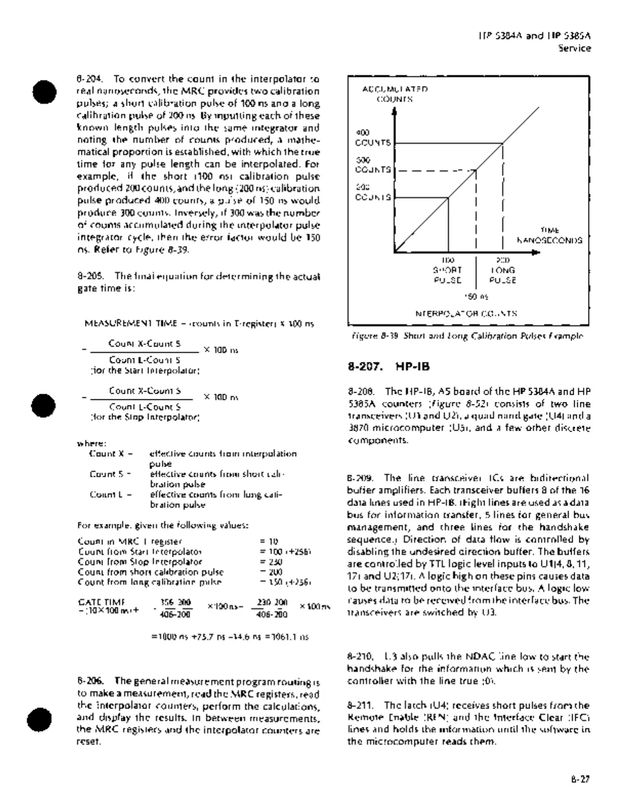
8-204. To
convert
the
count
in
the
interpolator
to
real nanoseconds,
the
MRC
provides
two
calibration
pulses; a
short
calibration
pulse
of
100
ns
and
a
long
calibration
pulse
of
200
ns.
By
inputting
each
of
these
known
length
pulses
into
the
same
integrator
and
noting
the
number
of
counts
produced,
a
mathe-
matical
proportion
is
established,
with
which
the
true
time
for
any pulse
length
can
be
interpolated.
For
example,
if
the
short
(100
ns)
calibration
pulse
produced
200
counts,
and
the
long
(200
ns)
calibration
pulse
produced
400
counts,
a
pulse
of
1SO
ns
would
produce
300
counts.
Inversely,
if
300
was
the
number
of
counts
accumulated
during
the
interpolator
pulse
integrator
cycle,
then
the
error
factor
would
be
1SO
ns.
Refer
to
Figure 8-39.
8-20S.
The
final
equation
for
determining
the
actual
gate
time
is:
MEASUREMENT
TIME = (counts in T-register) X
100
ns
Count X-Count S
+
---------
X
100
ns
Count L-Count S
(for the
Start
Interpolator)
Count X-Count S
_________
X100ns
Count L-Count S
(for the Stop Interpolator)
where:
Count
X=
effective counts from interpolation
pulse
CountS=
effective counts from short cali-
bration pulse
Count L = effective counts from long cali-
bration pulse
For
example, given the following values:
Count in MRC T register
=
10
Count from
Start
Interpolator
Count from Stop Interpolator
Count from short calibration pulse
Count from long calibration pulse
=
100
(+256)
=
230
GATE
TIME
=(10X100ns)+
356-200
406-200
X100ns-
=
200
=
150
(+256)
230-200
406-200
X100ns
=1000
ns
+75.7
ns
-14.6
ns
=1061.1
ns
8-206. The
general
measurement
program
routing
is
to
make
a
measurement,
read
the
MRC
registers, read
the
interpolator
counters,
perform
the
calculations,
and
display
the
results. In
between
measurements,
the
MRC
registers and
the
interpolator
counters
are
reset.
HP S384A
and
HP
S38SA
Service
ACCUMULATED
COUNTS
400
COUNTSr--------~~
300
COUNTS
200
COUNTS
r-----,(
100 200
SHORT LONG
PULSE PULSE
150 ns
INTERPOLATOR
COUNTS
TIME
NANOSECONDS
Figure
8-39.
Short
and
Long
Calibration
Pulses Example
8-207. HP-18
8-208. The HP-IB,
AS
board
of
the
HP
S384A
and HP
S38SA
counters
(figure
8-52) consists
of
two
line
transceivers (U1 and U2), a
quad
nand
gate (U4)
and
a
3870
microcomputer
(US), and a
few
other
discrete
components.
8-209. The
line
transceiver ICs are
bidirectional
buffer
amplifiers.
Each
transceiver
buffers
8
of
the
16
data lines used
in
HP-IB. (Eight lines are used
as
a data
bus
for
information
transfer, S lines
for
general bus
management,
and
three
lines
for
the
handshake
sequence.)
Direction
of
data
flow
is
controlled
by
disabling
the
undesired
direction
buffer.
The
buffers
are
controlled
by
TTL
logic
level
inputs
to
U1(4,
8,
11,
17) and U2(17). A
logic
high
on
these pins causes data
to
be
transmitted
onto
the
interface
bus. A
logic
low
causes data
to
be
received
from
the
interface
bus. The
transceivers are
switched
by U3.
8-210. U3 also pulls
the
NDAC
line
low
to
start
the
handshake
for
the
information
which
is
sent
by
the
controller
with
the
line
true
(0).
8-211. The latch (U4) receives
short
pulses
from
the
Remote
Enable (REN)
and
the
Interface
Clear
(IFC)
lines and
holds
the
information
until
the
software
in
the
microcomputer
reads
them.
8-27