HP
5384A and
HP
5385A
Service
8-161.
In digital
frequency
counters,
there
is
always
a possible
error
of
±1
count.
For increased measure-
ment
resolution in
the
HP
5384A/HP 5385A,
an
interpolator
circuit
is
used.
An
interpolator
circuit
measures the possible
time
difference
between
the
opening
and closing
of
the
counting
gate and clock
pulses
from
the
internal
time
base.
If
the
counting
gate does
not
open
at the same
time
a
clock
pulse
occurs and close
at
the
same
time
a
clock
pulse occurs
(n
number
of
events later), a
difference
occurs. The
difference
is
measured and the
information
is
sent
to
the
microcomputer
and used
in
calculating the
input
frequency,
eliminating
the
±1
count
uncertainty.
8-162. For
remote
control,
either
HP-Il
(A4 board)
or
HP-1
B (A5 boar.d)
is
used. Both boards make use
of
a
3870
microcomputer
to
communicate
with
the
3870
and
the
MRC
on
the
A 1
motherboard.
The
input/
output
(110) interface assembly contains
the
bus
tranceivers, address switches, and buffers. The A4
or
A5
1/0
assembly interfaces
directly
to
the
cable
connectors on
the
rear panel
of
the
instrument.
8-163. The
built-in
power
supply
is
a variable pulse
width,
switching
supply. The greater
the
duty
cycle
of
I
I
•
'
FlJTl/f"R',,
TRIG
LVL
1
ACC
B
the
pulse
width,
the
higher
the
output
power. The
supply
is
regulated
for
+5
volts
out.
External DC
input
power
of
9-15V and the
6V
power
from
the
optional
battery pack
is
also regulated
to
+5
volts. The
output
of
the
power
supply
is
protected
by a
crowbar
circuit
and a 2 amp fuse.
If
either
the
input
or
the
output
voltage
from
the
supplies goes
too
high,
the
crowbar
circuit
latches
on
and causes
the
fuse
to
open.
The
blown
fuse protects
the
rest
of
the
circuitry
from
the
excessive voltage.
8-164. The
optional
battery pack assembly
has
a
battery charger (A3 board)
for
automatic
recharging
of
the battery
whenever
external
power
is
connected.
External de
of
9-15V
or
unregulated
13.5
Vdcfrom
the
mains
input
supply
is
regulated
to
charge
the
lead
acid battery.
8-165. The
function
select keys
on
the
front
panel
keyboard (A2) select functions by sending a
command
to
the
microcomputer
(A 1
U2)
when
pressed. The
microcomputer
responds by
configuring
the
MRC
(A 1
U1)
to
perform
a
function
according
to
which
key
on
the
front
panel
has
been pressed.
387a.P
STB
t-----.:.:.''.::...0
..::.CAR=-::DS=--'-'PRESENCE=c=-=OET"-'.-----t--ir---A5-~is1
11'--------------+~·
vo
R4
1-P-ll:
~-------------f-,r,l
I
I I
L--------ol
L-------------------1-+-+++-----------~----
_,--t---'
A2
KEYB_£J~~';_c_D
____
~E=-----
---------l
CCif'FENSATED
"'
DISPLAY DRIVERS 11 POSITION
I KEYBOffiD I
I
UZI
s 3 8
l~
s
fj fj
H z I
~--------------------------J
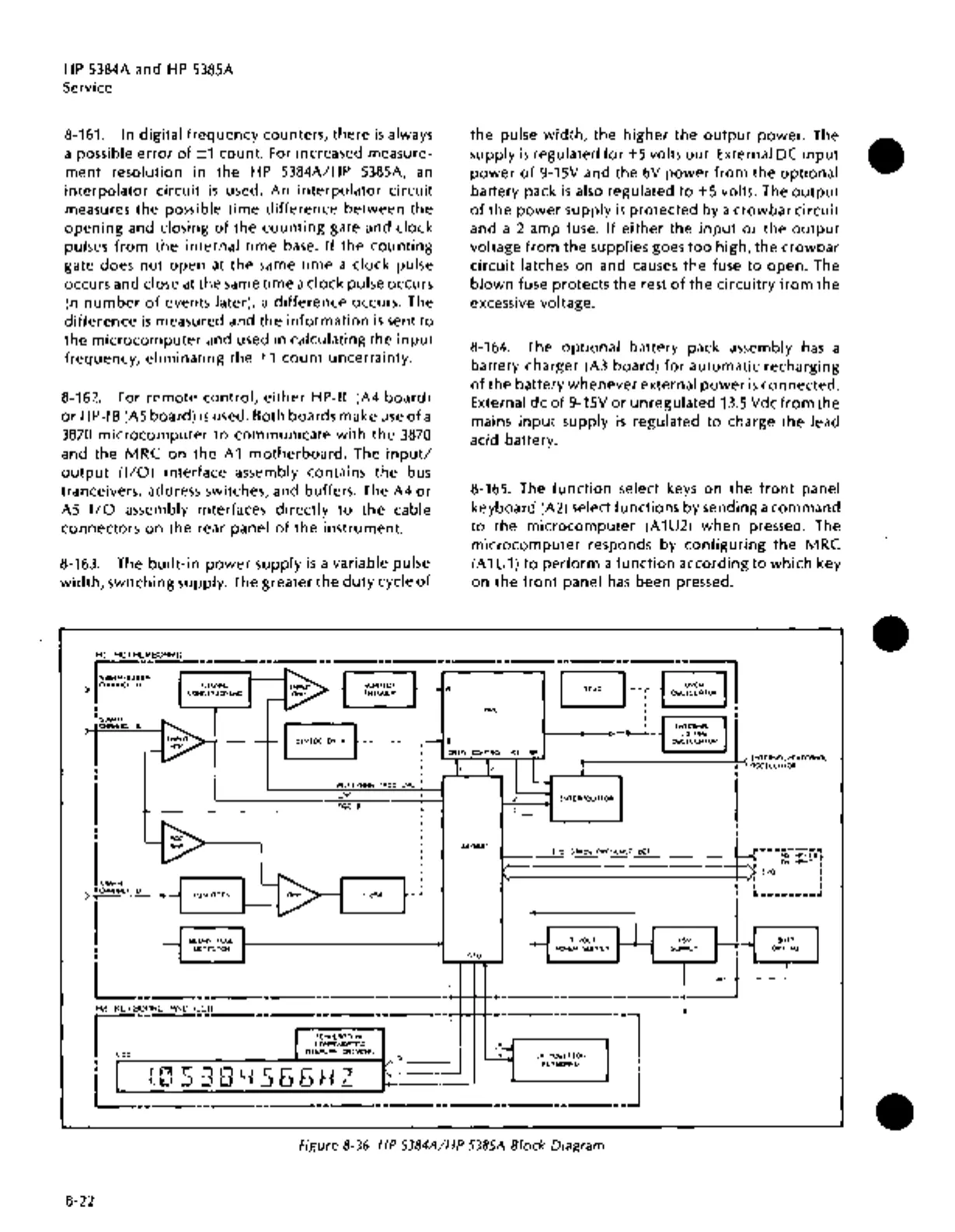
Figure 8-36. HP 5384A/HP 5385A Block Diagram
8-22
•
•
•