•
•
•
message) specify
the
particular message
within
the
classification. The Unlisten
command
frame,
for
ex-
ample,
would
be
100
0011111,
while
the
Interface
Clear
command
is
100
10010000.
The Send Data ready
message
is
101
01100000.
The space between
the
control
and data bits
is
for
clarity
only
and does
not
represent a
time
delay
or
any
other
delimiter.
8-227. The electrical
connection
from
one
instru-
ment
to
the
next
is
a
differential,
voltage-mode,
two-
wire,
100
ohm
balanced line. Both wires are
floating
with
respect
to
the
ground
connections
of
the instru-
ments.
One
of
the
wires
is
chosen
as
a reference and
the
voltage
of
the
other
wire
is
measured
only
with
respect
to
the reference. This
has
several advantages.
Device grounds need
not
be at
the
same potential. In
fact
there
can be rather large differences
with
no
effect. HP-IL avoids
the
problem
of
ground
loops in
an
interface system. Since noise pulses
tend
to
affect
both
wires equally,
the
balanced nature
of
HP-IL
HP
5384A and
HP
5385A
Service
strongly rejects these pulses. The same holds
true
for
noise radiation
from
the
system itself.
As
one
wire's
voltage rises the other's falls,
tending
to
cancel any
radiated
signal.
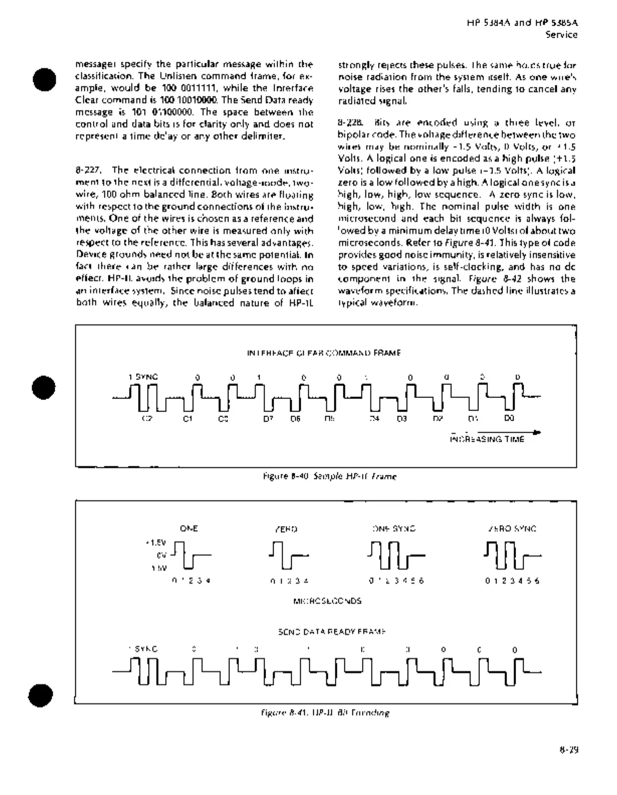
8-228.
Bits are
encoded
using a
three
level,
or
bipolar
code. The voltage
difference
between
the
two
wires may be
nominally
-1.5
Volts, 0 Volts,
or
+1.5
Volts. A logical
one
is
encoded
as
a high pulse (+1.5
Volts)
followed
by a
low
pulse (-1.5 Volts). A logical
zero
is
a
low
followed
by a high. A logical
one
sync
is
a
high,
low,
high,
low
sequence. A zero sync
is
low,
high,
low,
high. The
nominal
pulse
width
is
one
microsecond and each
bit
sequence
is
always
fol-
lowed
by a
minimum
delay
time
(OVolts)
of
about
two
microseconds. Refer
to
Figure 8-41. This
type
of
code
provides
good
noise
immunity,
is
relatively insensitive
to
speed variations,
is
self-clocking, and
has
no
de
component
in
the signal. Figure 8-42 shows the
waveform specifications. The dashed
line illustrates a
typical waveform.
INTERFACE
CLEAR
COMMAND
FRAME
1
SYNC
0
C2
C1
ONE
+1.5V
IG--
OV
-1.5V
0 1 2 3 4
1 SYNC
0
0
co
0
0 0
0
D7 D6
D5
D4
D3
Figure 8-40. Sample HP-IL Frame
ZERO
ONE
SYNC
0 1 2 3 4
0 1
::.
3 4 5 6
MICROSECONDS
SEND
DATA
READY FRAME
0 0
Figure 8-41. HP-IL Bit
Encoding
0
0 0
D2
D1
DO
INCREASING
TIME
ZERO
SYNC
0
1 2 3 4 5 6
0
0
0
8-29