HP
5384A and HP 5385A
General
Information
1-4
Table 1-1.
Models
HP
5384A
and
HP 5385A Specifications
(Continued)
PERIOD A
Range:
10
ns
to
0.1
s
LSD
Displayed:
.001
fs
to
10
ns
LSD:
__
4
_n_s
__
X
period
Gate
Time
Resolution:
±
LSD
± (1.4 X Trigger Error + 1 ns rms)
Gate
Time
X Per
Accuracy: ±
Resolution
± Time Base Error X Period
OPTIONS
Option
001
(HP
5384A),
TXCO
Timebase
Frequency:
10
MHz
Aging Rate: <1 X 1Q-7/mo.
Temperature:
±1 X 10⁻⁶,
oo
to
40°C ref.
to
25°C.
Line Voltage:
<5
X 10-8 for ±10% variation.
Option 003, HP-IL
All
HP-Il
programmable
functions,
controls,
and
operations
are
the
same
as
those
for HP-IB
except
for interface functions
Auto
Address
and
Parallel Poll, which
are
also
included.
R,
AH, SH1,
D,
l1,
(T1-S),
CO,
DC2,
DT1,
PP1,
SR2,
AA
1, Rl2,
PDO,
DD1.
Option 004, Oven Timebase
Frequency:
10
MHz
Aging Rate: <3
.x
10-8/mo.
(2)
Temperature:
±1 X 10⁻⁷, 0°
to
50°C ref.
to
25°C.
Line Voltage:
<2
X 10-9 for a ±10% variation.
Battery
Operation:
The
instrument
operates
for 3
hours
(typical) with
option
004.
Option 005, Battery
Type: Sealed
lead-acid;
not
covered
under
instrument
warranty.
Capacity:
Typically 4
hours
of
operation
at 25°C
(1).
Recharge
Time: Typically 16
hours
to
98%
of
full
charge
in
instrument
STBY
(Standby)
mode.
Battery Low
Annunciator:
Enabled
20
minutes
prior
to
instrument
shutdown
nominally.
Line
Failure
Protection:
Instrument
automatically
switches
to
battery
in
case
of
line failure.
Weight:
Option
005
adds
1.4 kg.
(3
lbs.)
to
weight
of
instrument.
(1)
without
Option
004 installed.
HP-Il
replaces
HP-IB
when
Option
005
is
ordered
from
the
factory.
HP-18
1/0
Interface
Programmable
Functions:
Frequency
A,
Frequency
B,
Period
A.
Programmable
Controls:
X20
Attn A,
FILTER
A, MAN
LEVEL
A/B,
Gate
Time.
Display: Normal,
Increment,
Decrement,
Remote,
local
Miscellaneous
Functions
and
Operating
Commands:
Diagnostics, 10
MHz
Check,
reset,
initialize, Wait
To
Send
ON/OFF
Device
ID.
Interface
Functions:
Device Clear,
Group
Execute Trigger
Interface Clear,
local,
local
lockout,
Send
Status,
Remote,
Service Request.
SH1, AH1,
TS,
TEO,
l4,
LEO,
SR1,
Rl1,
PPO,
DC1,
DT1,
CO,
E1.
Data
Output:
Output
will
be
maximum
resolution
for
the
gate
time
selected
and
is
not
affected
by
the
front
panel
Display
Digits keys.
Format: 17
characters
plus CR
and
LF
(blanks may
be
inserted).
Rate:
4
readings/s
maximum
at
.1
s gate.
Talk
only:
Set with
address
switch=31.
DEFINITIONS
Measurement
Gate
Time:
Selected
value
±15% +
up
to
1
period
of
input.
Dynamic
Range:
Minimum
to
maximum
input
voltage
swing
allowed
for
correct
frequency
counting.
LSD
Displayed:
Dependent
on
gate
time,
input
signal,
and
DISPLAY
DIGITS
control.
In
NORM
mode,
8 digits
are
displayed. Using
the
display
control,
up
to
11
digits may
be
present
for
frequency
measurements,
8 digits maximum
for
period.
LSD:
Unit value
of
least significant digit
rounded
to
the
nearest
decade,
i.e., 4 Hz
-1
Hz, 6 Hz
-10
Hz.
Trigger Error:
Channel
A:
y,..,.(
e-:-i
):-;;:2--:+-(-:-e-n
):-;;:2-
----,------'------
s rms,
Input slew rate at trigger
point
where
ei
and
en
are
input
noise voltages (rms) for
the
counter
and
signal, respectively, for a 100
MHz
bandwidth.
ei
::;
100
11-V
rms,
Channel
B:
negligible
due
to
high signal slew rate at
the
trigger point.
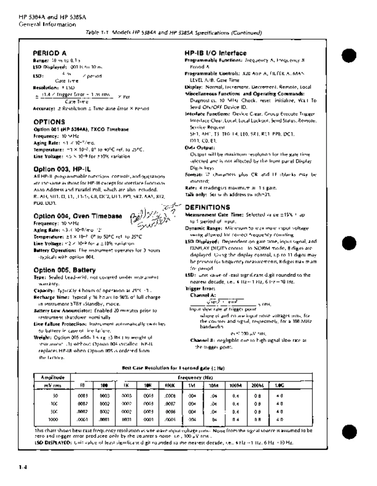
Best
Case
Resolution
for 1
second
gate
(±Hz)
Amplitude
Frequency
(Hz)
mVrms
10
100
lK
lOK
lOOK
1M 10M
lOOM
200M
l.OG
so
.0003
.0003
.0003
.0003 .0008 .004
.04 0.4 0.8
4.0
100
.0002
.0002
.0002
.0003 .0007 .004
.04
0.4
0.8
4.0
500
.0002
.0002
.0002
.0003 .0006 .004
.04 0.4 0.8
4.0
1000 .0001 .0001 .0001 .0001 .0005
.004 .04 0.4 0.8
4.0
Th1s
chart
shows
best
case
frequency
resolution
vs
sine wave
input
voltage
(rms). Noise
from
the
signal
source
is
assumed
to
be
zero
and
tngger
error
produced
only
by
the
counter's
noise
(i.e., 100
11-V
rms).
LSD
DISPLAYED:
Unit
value
of
least significant digit
rounded
to
the
nearest
decade,
i.e.,
4Hz-1Hz,
6Hz-10Hz.
•
•
•