95
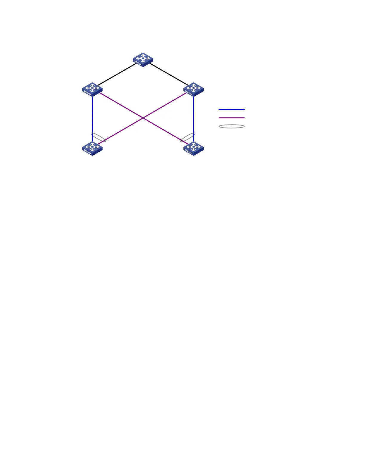
Figure 24 Network diagram for single smart link group configuration
Device A
Device E
Device DDevice C
Device B
GE
1
/0
/
1
GE
1
/
0
/2
GE
1
/
0
/
1
GE
1
/0
/
1
GE
1
/
0
/
2
GE
1
/
0
/
2
GE1/0/3
GE1/0/1
GE1/0/2
GE1/0/3
GE1/0/1
GE1/0/2
Master link
Slave link
Smart link group
Configuration procedure
1. Configure Device C.
# Create VLANs 1 through 30, map these VLANs to MSTI 1, and activate the MST region configuration.
<DeviceC> system-view
[DeviceC] vlan 1 to 30
[DeviceC] stp region-configuration
[DeviceC-mst-region] instance 1 vlan 1 to 30
[DeviceC-mst-region] active region-configuration
[DeviceC-mst-region] quit
# Shut down ports GigabitEthernet 1/0/1 and GigabitEthernet 1/0/2, disable STP on them, and
configure them as trunk ports that permit VLANs 1 through 30.
[DeviceC] interface gigabitethernet 1/0/1
[DeviceC-GigabitEthernet1/0/1] shutdown
[DeviceC-GigabitEthernet1/0/1] undo stp enable
[DeviceC-GigabitEthernet1/0/1] port link-type trunk
[DeviceC-GigabitEthernet1/0/1] port trunk permit vlan 1 to 30
[DeviceC-GigabitEthernet1/0/1] quit
[DeviceC] interface gigabitethernet 1/0/2
[DeviceC-GigabitEthernet1/0/2] shutdown
[DeviceC-GigabitEthernet1/0/2] undo stp enable
[DeviceC-GigabitEthernet1/0/2] port link-type trunk
[DeviceC-GigabitEthernet1/0/2] port trunk permit vlan 1 to 30
[DeviceC-GigabitEthernet1/0/2] quit
# Create smart link group 1, and configure all VLANs mapped to MSTI 1 as the protected VLANs.
[DeviceC] smart-link group 1
[DeviceC-smlk-group1] protected-vlan reference-instance 1
# Configure GigabitEthernet 1/0/1 as the master port and GigabitEthernet 1/0/2 as the slave port for
smart link group 1.
[DeviceC-smlk-group1] port gigabitethernet 1/0/1 master
[DeviceC-smlk-group1] port gigabitethernet 1/0/2 slave
 Loading...


