29
Display the TST result on the
specified MEP
display cfd tst [ service-instance instance-id
[ mep mep-id ] ] [ | { begin | exclude |
include } regular-expression ]
Clear the one-way DM result on
the specified MEP
reset cfd dm one-way history [ service-
instance instance-id [ mep mep-id ] ]
Clear the TST result on the
specified MEP
reset cfd tst [ service-instance instance-id [
mep mep-id ] ]
CFD configuration example
Network requirements
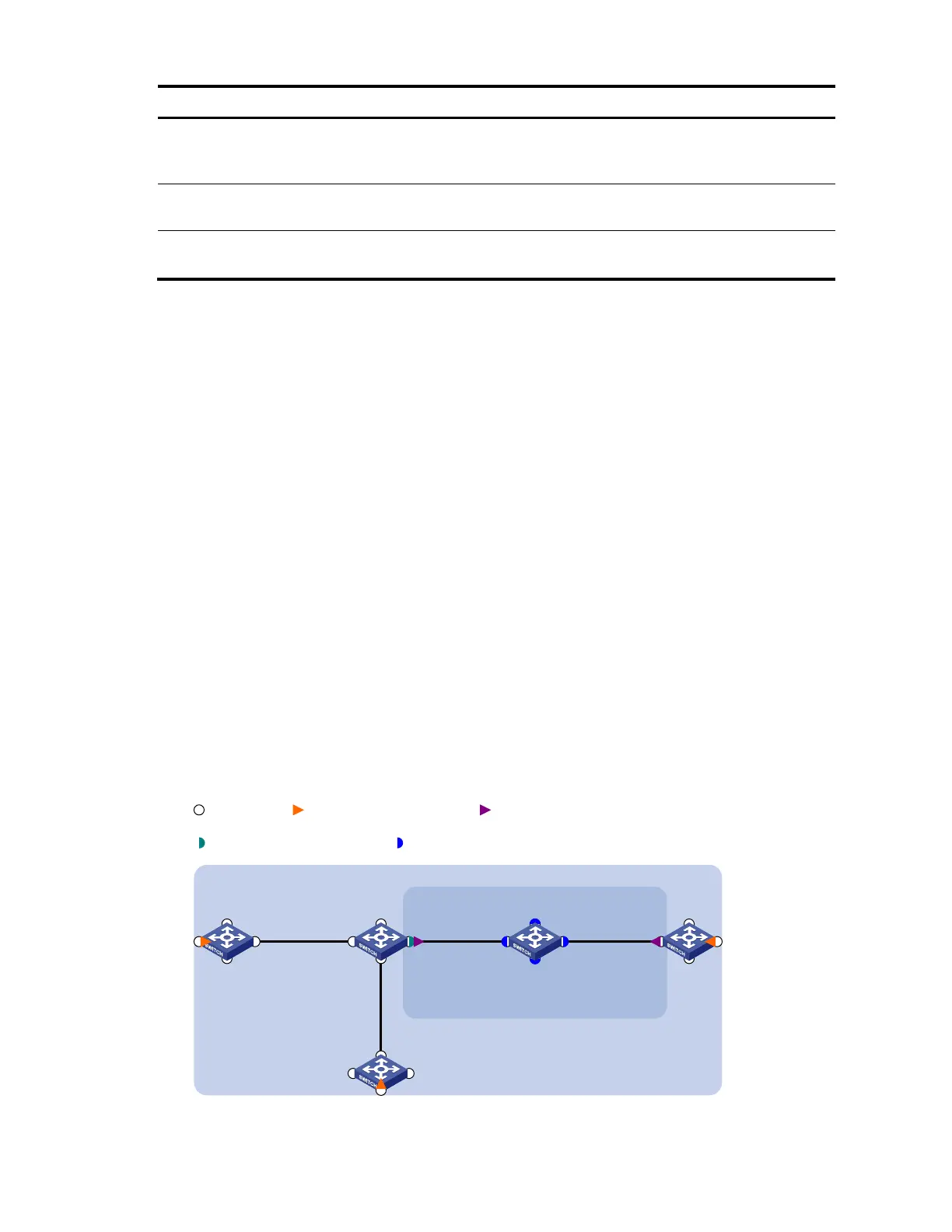
As shown in Figure 8:
The network comprises five devices and is divided into two MDs: MD_A (level 5) and MD_B (level
3). All ports belong to VLAN 100, and the MAs in the two MDs all serve VLAN 100.
MD_A has three edge ports: GigabitEthernet 1/0/1 on Device A, GigabitEthernet 1/0/3 on
Device D, and GigabitEthernet 1/0/4 on Device E, and they are all inward-facing MEPs. MD_B has
two edge ports: GigabitEthernet 1/0/3 on Device B and GigabitEthernet 1/0/1 on Device D, and
they are both outward-facing MEPs.
In MD_A, Device B is designed to have MIPs when its port is configured with low level MEPs. Port
GigabitEthernet 1/0/3 is configured with MEPs of MD_B, and the MIPs of MD_A can be configured
on this port. You should configure the MIP generation rule of MD_A as explicit.
The MIPs of MD_B are designed on Device C, and are configured on all ports. You should configure
the MIP generation rule as default.
Configure CC to monitor the connectivity among all the MEPs in MD_A and MD_B. Configure to use
LB to locate link faults, and use the AIS function to suppress the error alarms reported.
After the status information of the entire network is obtained, use LT, LM, one-way DM, two-way DM,
and TST to detect link faults.
Figure 8 Network diagram for CFD configuration
GE1/0/2
GE1/0/1 GE1/0/3
GE1/0/4
Device A
GE1/0/2
GE1/0/1 GE1/0/3
GE1/0/4
Device B
GE1/0/2
GE1/0/1 GE1/0/3
GE1/0/4
Device C
GE1/0/2
GE1/0/1 GE1/0/3
GE1/0/4
Device D
GE1/0/2
GE1/0/1 GE1/0/3
GE1/0/4
Device E
MD_A
MD_B
VLAN 100
Port Inward-facing MEP Outward-facing MEP
MIP with explicit rule MIP with default rule