59
Device B is the master node of Ring 1 in Domain 2. With such configurations, traffic of different VLANs
can be transmitted on different links to achieve load balancing in the single-ring network.
RRPP ring group
In an edge node RRPP ring group, only an activated subring with the lowest domain ID and ring ID can
send Edge-Hello packets. In an assistant-edge node RRPP ring group, any activated subring that has
received Edge-Hello packets will forward these packets to the other activated subrings. With an edge
node RRPP ring group and an assistant-edge node RRPP ring group configured, only one subring sends
Edge-Hello packets on the edge node, and only one subring receives Edge-Hello packets on the assistant-
edge node, reducing CPU workload.
As shown in Figure 17, Device B is the edge node of Ring 2 and Ring 3, and Device C is the assistant-
edge node of Ring 2 and Ring 3. Device B and Device C must send or receive Edge-Hello packets
frequently. If more subrings are configured or if load balancing is configured for multiple domains, Device
B and Device C will send or receive a mass of Edge-Hello packets.
To reduce Edge-Hello traffic, you can assign Ring 2 and Ring 3 to an RRPP ring group configured on the
edge node Device B and assign Ring 2 and Ring 3 to an RRPP ring group configured on Device C. After
such configurations, if all rings are activated, only Ring 2 on Device B sends Edge-Hello packets.
Typical RRPP networking
Here are several typical networking applications.
Single ring
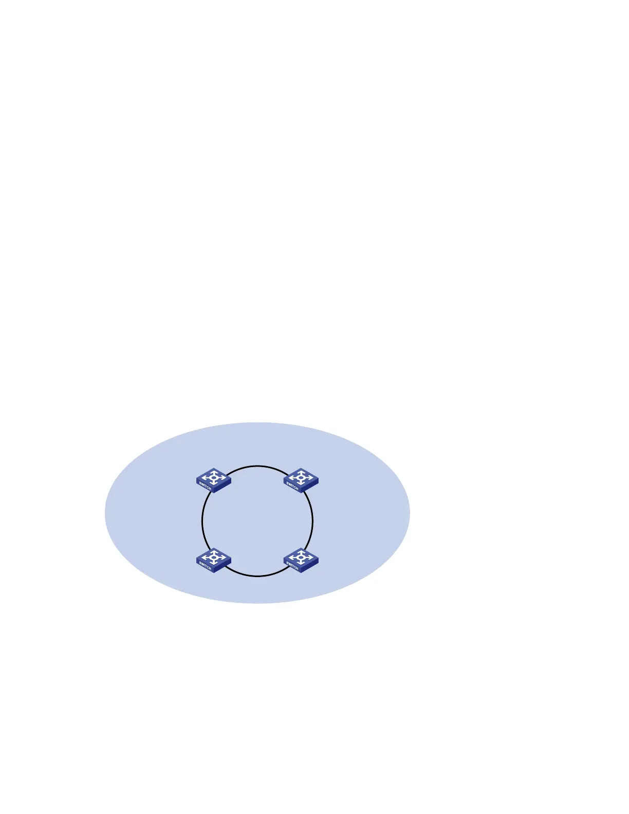
Figure 14 shows a single ring in the network topology. You only need to define one RRPP domain.
Figure 14 Schematic diagram for a single-ring network
Device A
Master node
Device D
Transit node
Domain 1
Ring 1
Device C
Transit node
Device B
Transit node
Tangent rings
As Figure 15 shows, a tangent-ring network includes two or more rings in the network topology with only
one common node between rings. You must define an RRPP domain for each ring.