99
Received flush packets : 5
Receiving interface of the last flush packet : GigabitEthernet1/0/3
Receiving time of the last flush packet : 16:25:21 2009/02/21
Device ID of the last flush packet : 000f-e23d-5af0
Control VLAN of the last flush packet : 1
Multiple smart link groups load sharing configuration example
Network requirements
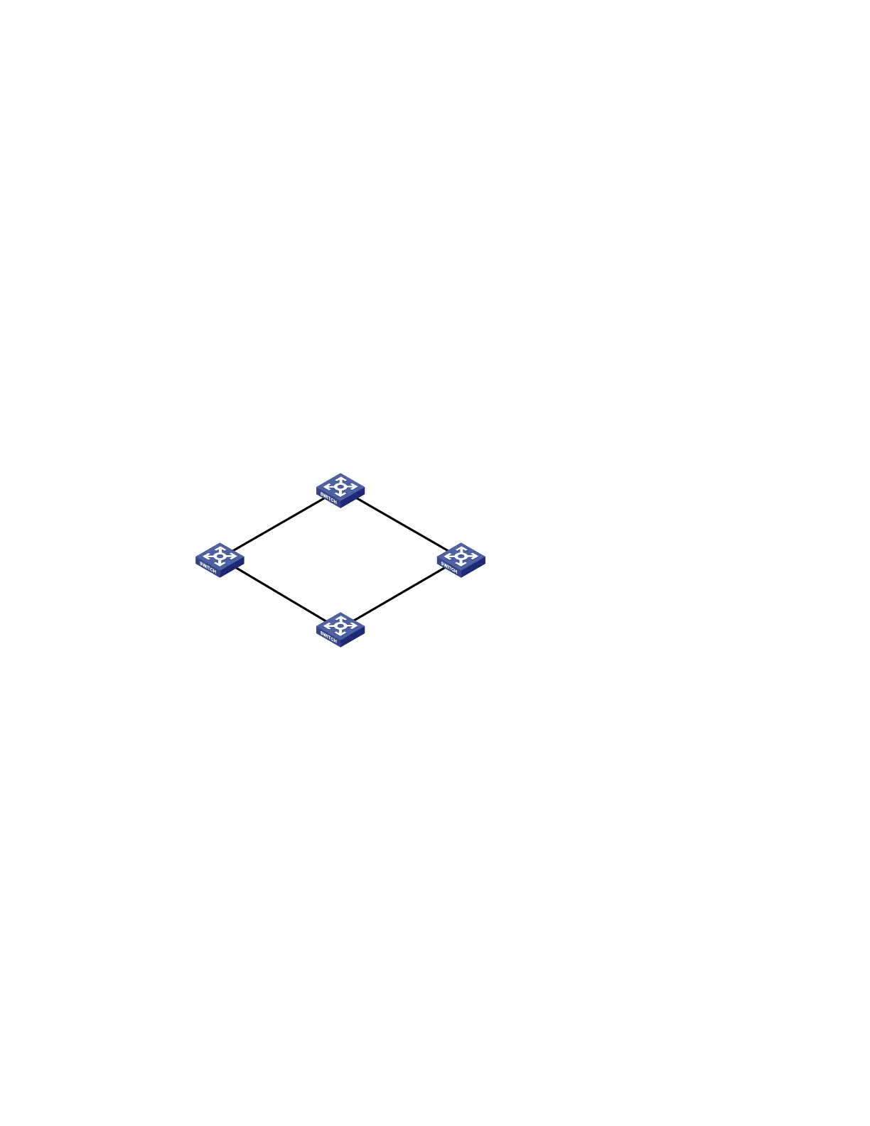
As shown in Figure 25:
Device C is a smart link device, and Device A, Device B, and Device D are associated devices.
Traffic of VLANs 1 through 200 on Device C are dually uplinked to Device A by Device B and
Device D.
Implement dual uplink backup and load sharing on Device C:
Traffic of VLANs 1 through 100 is uplinked to Device A by Device B.
Traffic of VLANs 101 through 200 is uplinked to Device A by Device D.
Figure 25 Network diagram for multiple smart link groups load sharing configuration
Device A
Device DDevice B
GE
1
/0
/
1
GE
1
/
0
/
2
GE1
/
0
/
1
GE
1
/
0
/
1
GE
1
/
0
/
2
GE
1
/
0
/
2
Device C
GE
1
/
0
/
1
GE
1
/
0
/
2
Configuration procedure
1. Configure Device C.
# Create VLAN 1 through VLAN 200. Map VLANs 1 through 100 to MSTI 1. Map VLANs 101 through
200 to MSTI 2, and activate MST region configuration.
<DeviceC> system-view
[DeviceC] vlan 1 to 200
[DeviceC] stp region-configuration
[DeviceC-mst-region] instance 1 vlan 1 to 100
[DeviceC-mst-region] instance 2 vlan 101 to 200
[DeviceC-mst-region] active region-configuration
[DeviceC-mst-region] quit
# Shut down ports GigabitEthernet 1/0/1 and GigabitEthernet 1/0/2, disable STP on them, and
configure them as trunk ports that permit VLANs 1 through 200.
[DeviceC] interface gigabitethernet 1/0/1
[DeviceC-GigabitEthernet1/0/1] shutdown
[DeviceC-GigabitEthernet1/0/1] undo stp enable

 Loading...


