69
display rrpp statistics domain domain-id [ ring
ring-id ] [ | { begin | exclude | include }
regular-expression ]
reset rrpp statistics domain domain-id [ ring
ring-id ]
RRPP configuration examples
Single ring configuration example
Networking requirements
Device A, Device B, Device C, and Device D form RRPP domain 1. Specify the primary control VLAN
of RRPP domain 1 as VLAN 4092. RRPP domain 1 protects VLANs 1 through 30.
Device A, Device B, Device C, and Device D form primary ring 1.
Specify Device A as the master node of primary ring 1, GigabitEthernet 1/0/1 as the primary
port, and GigabitEthernet 1/0/2 as the secondary port.
Specify Device B, Device C, and Device D as the transit nodes of primary ring 1. Specify their
GigabitEthernet 1/0/1 as the primary port, and GigabitEthernet 1/0/2 as the secondary port.
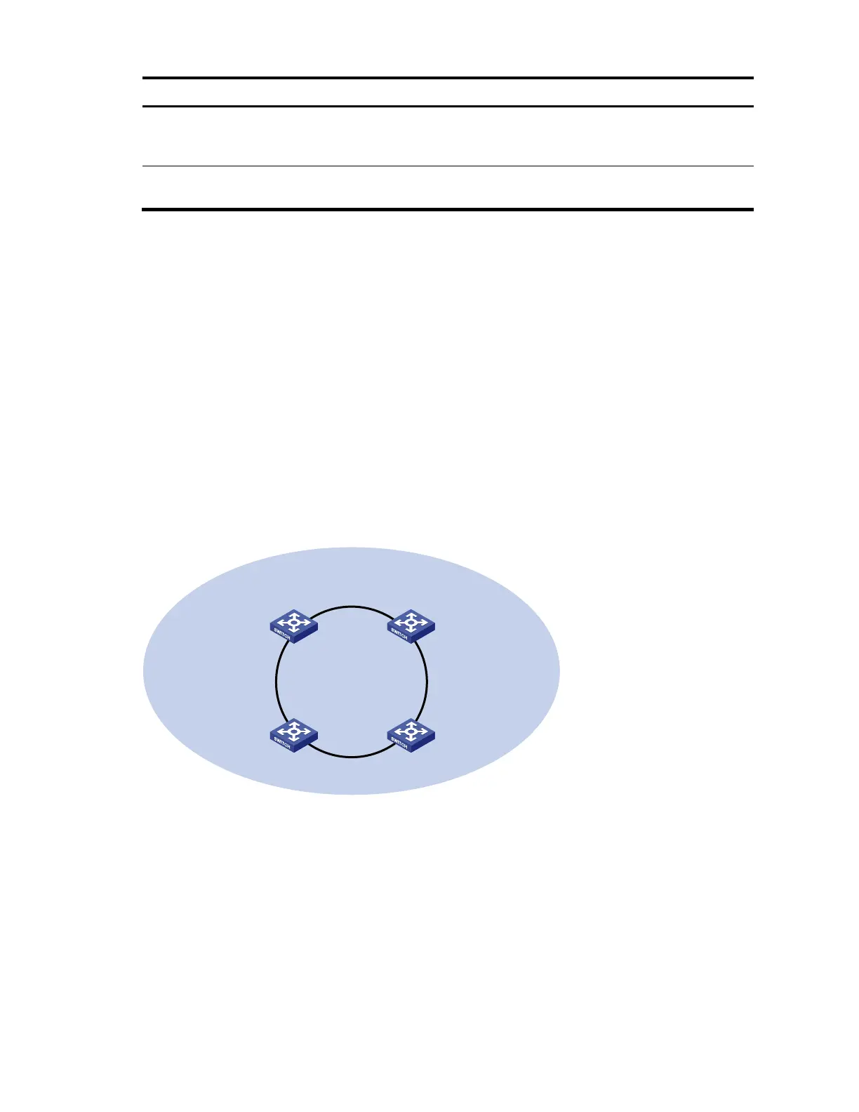
Figure 20 Network diagram for single ring configuration
Device A
Master node
Device D
Transit node
Domain 1
Ring 1
GE1/0/2
GE1/0/1
GE1/0/2
GE1/0/1
GE1/0/2
GE1/0/1
GE1/0/2
GE1/0/1
Device C
Transit node
Device B
Transit node
Configuration procedure
1. Configure Device A.
# Create VLANs 1 through 30, map these VLANs to MSTI 1, and activate the MST region configuration.
<DeviceA> system-view
[DeviceA] vlan 1 to 30
[DeviceA] stp region-configuration
[DeviceA-mst-region] instance 1 vlan 1 to 30
[DeviceA-mst-region] active region-configuration
[DeviceA-mst-region] quit