13
Display the statistics on Ethernet
OAM link error events after an
Ethernet OAM connection is
established
display oam link-event { local | remote } [
interface interface-type interface-number ] [ | {
begin | exclude | include } regular-expression
]
Display the information about an
Ethernet OAM connection
display oam { local | remote } [ interface
interface-type interface-number ] [ | { begin |
exclude | include } regular-expression ]
Clear statistics on Ethernet OAM
packets and Ethernet OAM link
error events
reset oam [ interface interface-type interface-
number ]
Available in user
view only
Ethernet OAM configuration example
Network requirements
On the network shown in Figure 2, perform the following operations:
Enable Ethernet OAM on Switch A and Switch B to auto-detect link errors between the two devices
Monitor the performance of the link between Switch A and Switch B by collecting statistics about the
error frames received by Switch A
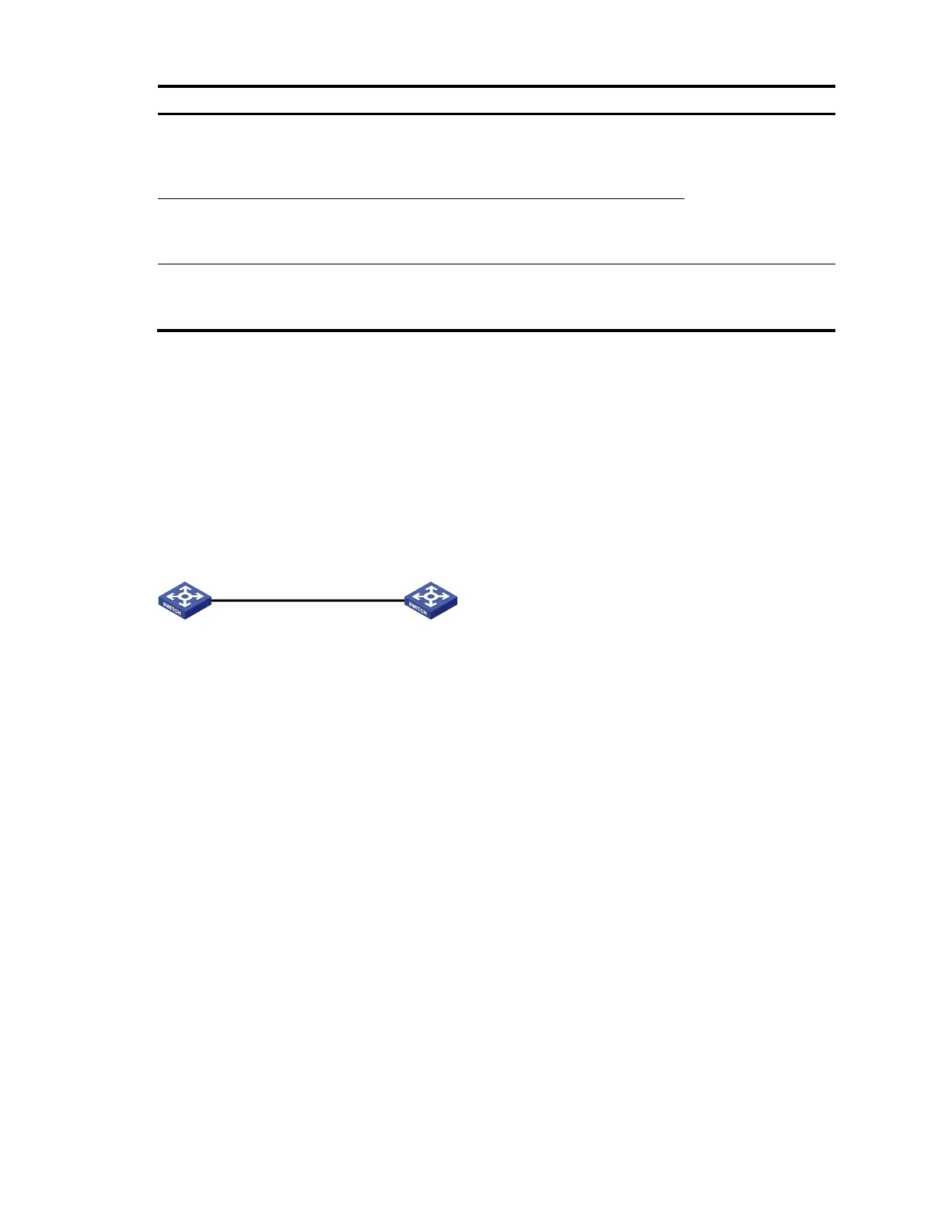
Figure 2 Network diagram for Ethernet OAM configuration
GE1/0/1 GE1/0/1
Switch A Switch B
Configuration procedure
1. Configure Switch A.
# Configure GigabitEthernet 1/0/1 to operate in passive Ethernet OAM mode and enable Ethernet
OAM for it.
<SwitchA> system-view
[SwitchA] interface gigabitethernet 1/0/1
[SwitchA-GigabitEthernet1/0/1] oam mode passive
[SwitchA-GigabitEthernet1/0/1] oam enable
[SwitchA-GigabitEthernet1/0/1] quit
# Set the errored frame detection interval to 20 seconds and set the errored frame event triggering
threshold to 10.
[SwitchA] oam errored-frame period 20
[SwitchA] oam errored-frame threshold 10
2. Configure Switch B.
# Configure GigabitEthernet 1/0/1 to operate in active Ethernet OAM mode (the default) and enable
Ethernet OAM for it.
<SwitchB> system-view
[SwitchB] interface gigabitethernet 1/0/1
[SwitchB-GigabitEthernet1/0/1] oam mode active