61
Figure 17 Schematic diagram for a dual-homed-ring network
Device A
Master node
Device D
Transit node
Domain 1
Ring 1
Device C
Assistant edge node
Device B
Edge node
Ring 2
Device E
Master node
Device F
Master node
Ring 3
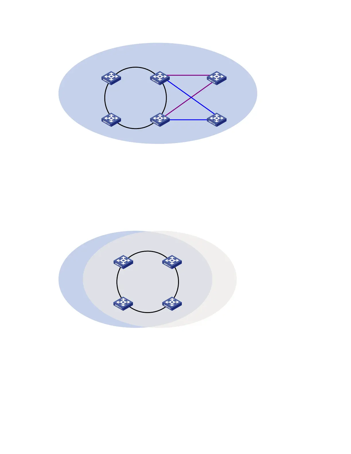
Single-ring load balancing
In a single-ring network, you can achieve load balancing by configuring multiple domains.
As shown in Figure 18, Ring 1 is configured as the primary ring of both Domain 1 and Domain 2.
Domain 1 and Domain 2 are configured with different protected VLANs. In Domain 1, Device A is
configured as the master node of Ring 1. In Domain 2, Device B is configured as the master node of Ring
1. Such configurations enable the ring to block different links based on VLANs, and single-ring load
balancing is achieved.
Figure 18 Schematic diagram for a single-ring load balancing network
Domain 1 Ring 1
Device A Device B
Device D Device C
Domain 2
Intersecting-ring load balancing
In an intersecting-ring network, you can also achieve load balancing by configuring multiple domains.
As shown in Figure 19, Ring 1 is the primary ring and Ring 2 is the subring in both Domain 1 and
Domain 2. Domain 1 and Domain 2 are configured with different protected VLANs. Device A is
configured as the master node of Ring 1 in Domain 1. Device D is configured as the master node of Ring
1 in Domain 2. Device E is configured as the master node of Ring 2 in both Domain 1 and Domain 2.
However, different ports on Device E are blocked in Domain 1 and Domain 2. With the configurations,
you can enable traffic of different VLANs to travel over different paths in the subring and primary ring to
achieve intersecting-ring load balancing.
 Loading...


