60
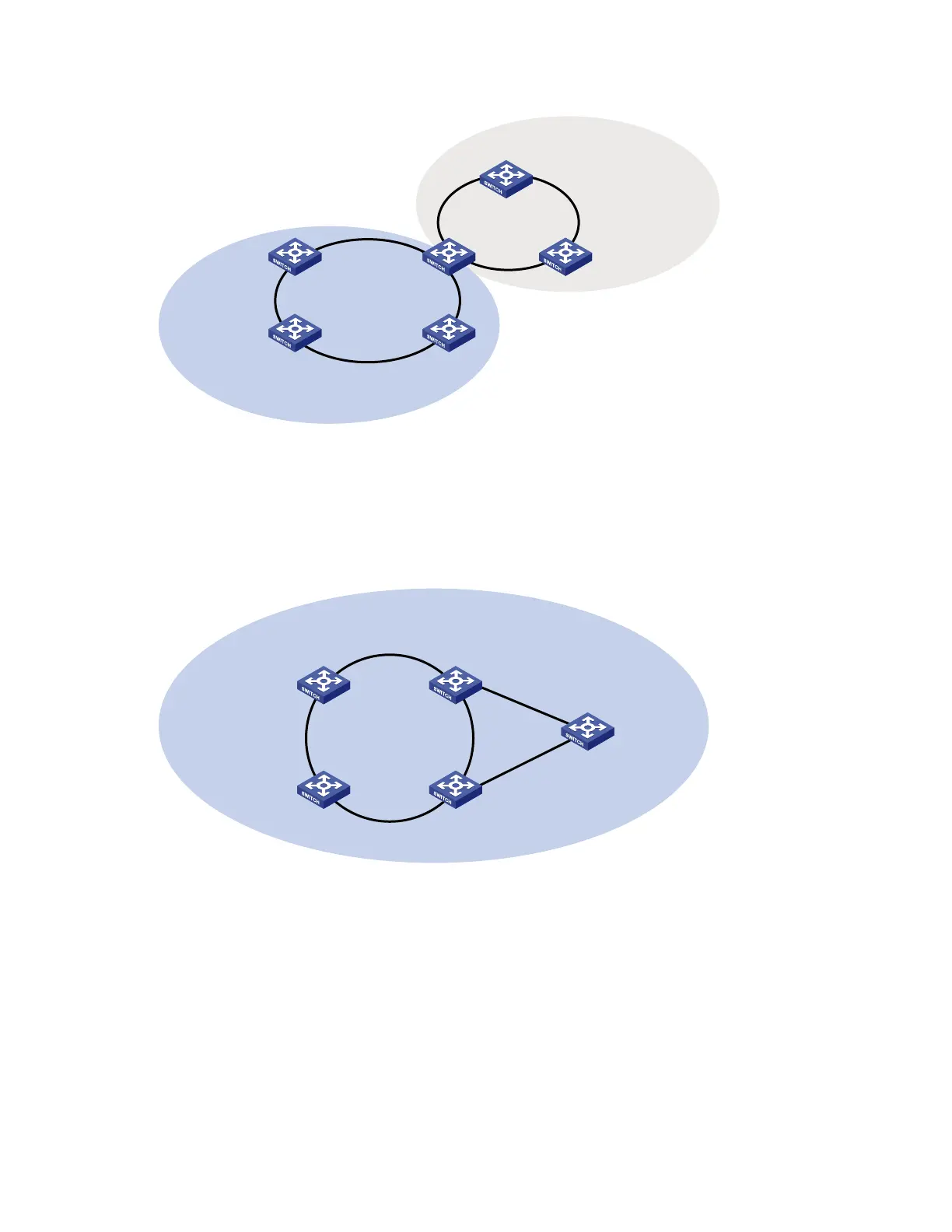
Figure 15 Schematic diagram for a tangent-ring network
Ring 1
Device A
Master node
Domain 1
Device D
Transit node
Ring 2
Domain 2
Device C
Transit node
Device B
Transit node
Device E
Master node
Device F
Transit node
Intersecting rings
As shown in Figure 16, two or more rings are in the intersecting-ring network topology, with two common
nodes between rings. You only need to define an RRPP domain and configure one ring as the primary
ring and the other rings as subrings.
Figure 16 Schematic diagram for an intersecting-ring network
Device A
Master node
Device D
Transit node
Domain 1
Ring 1
Device C
Assistant edge node
Device B
Edge node
Ring 2
Device E
Master node
Dual-homed rings
As shown in Figure 17, two or more rings are in the dual-homed rings network topology, with two similar
common nodes between rings. You only need to define an RRPP domain and configure one ring as the
primary ring and the other rings as subrings.