78
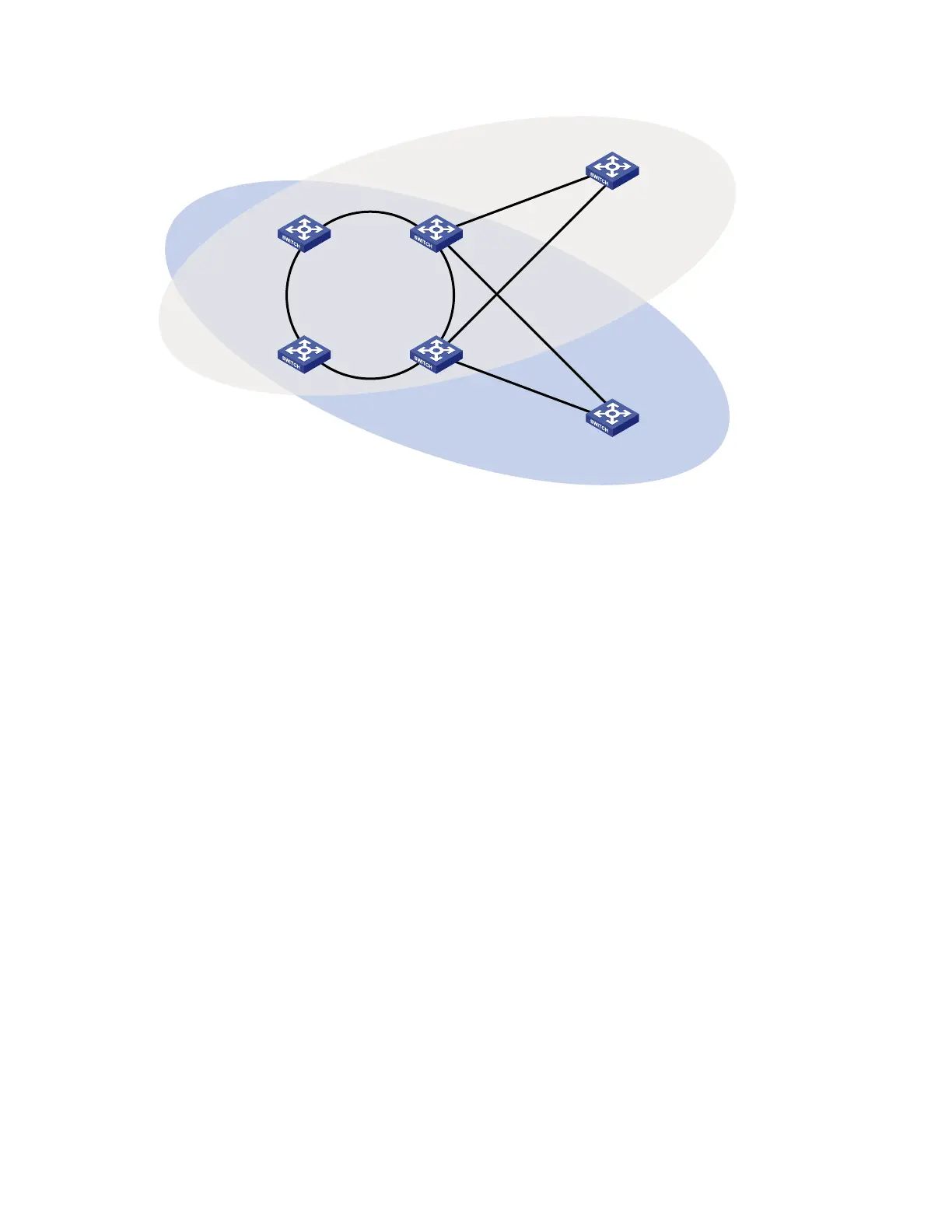
Figure 22 Network diagram for intersecting-ring load balancing configuration
Device A
Master node
Device D
Transit node
Domain 1
Ring 1
GE1/0/2
GE1/0/1
GE1/0/2
GE1/0/1
GE1/0/2
GE1/0/1
GE1/0/2
GE1/0/1
Device B
Assistant edge node
Device C
Edge node
Ring 2
GE1/0/3
GE1/0/1
GE1/0/2
Device E
Master node
Ring 3
GE1/0/4
GE1/0/3
GE1/0/4
GE1/0/2
GE1/0/1
Device F
Master node
Domain 2
Configuration procedure
1. Configure Device A.
# Create VLANs 10 and 20, map VLAN 10 to MSTI 1 and VLAN 20 to MSTI 2, and activate MST region
configuration.
<DeviceA> system-view
[DeviceA] vlan 10
[DeviceA-vlan10] quit
[DeviceA] vlan 20
[DeviceA-vlan20] quit
[DeviceA] stp region-configuration
[DeviceA-mst-region] instance 1 vlan 10
[DeviceA-mst-region] instance 2 vlan 20
[DeviceA-mst-region] active region-configuration
[DeviceA-mst-region] quit
# Disable physical state change suppression and STP on GigabitEthernet 1/0/1 and GigabitEthernet
1/0/2, and configure the two ports to trust the 802.1p precedence of the received packets. Configure the
two ports as trunk ports, remove them from VLAN 1, and assign them to VLAN 10 and VLAN 20.
[DeviceA] interface gigabitethernet 1/0/1
[DeviceA-GigabitEthernet1/0/1] undo link-delay
[DeviceA-GigabitEthernet1/0/1] undo stp enable
[DeviceA-GigabitEthernet1/0/1] qos trust dot1p
[DeviceA-GigabitEthernet1/0/1] port link-type trunk
[DeviceA-GigabitEthernet1/0/1] undo port trunk permit vlan 1
[DeviceA-GigabitEthernet1/0/1] port trunk permit vlan 10 20
[DeviceA-GigabitEthernet1/0/1] quit
[DeviceA] interface gigabitethernet 1/0/2
[DeviceA-GigabitEthernet1/0/2] undo link-delay