4
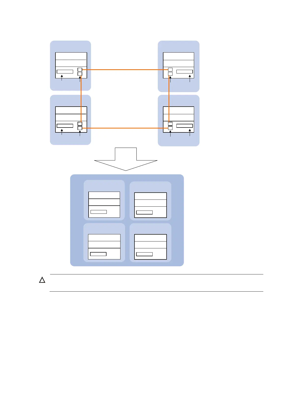
Figure 3 IRF implementation schematic diagram (with four member switches)
IRF link
After an IRF
is formed.
Suppose
Device A is
the master
Master
(MemberID=1)
Slave
(MemberID=3)
Physical IRF
port
Physical IRF
port
IRF-Port2 IRF-Port1
Service
interface
Service
interface
IRF
Active MPU of the IRF
Standby MPU of the IRF
Active MPU of the
member
Device A
(MemberID=1)
Device B
(MemberID=2)
IRF-Port2
IRF-Port2
Service
interface
Service
interface
Standby MPU of the
member
Active MPU of the
member
Standby MPU of the
member
IRF-Port1
Physical IRF
port
Physical IRF
port
Active MPU of the
member
Standby MPU of the
member
Device C
(MemberID=3)
Device D
(MemberID=4)
Active MPU of the
member
Standby MPU of the
member
IRF-Port1
IRF-Port2
IRF-Port1
Slave
(MemberID=2)
Standby MPU of the IRF
Standby MPU of the IRF
Slave
(MemberID=4)
Standby MPU of the IRF
Standby MPU of the IRF Standby MPU of the IRF
Standby MPU of the IRF
CAUTION:
In an IRF fabric, each slave switch must have at least one MPU to work normally.
This section uses Figure 2 to explain the concepts that you might encounter when working with IRF.
Operating mode
A switch can operate in one of the following two modes:
• Standalone mode—The switch cannot form an IRF fabric with other switches.
• IRF mode—The switch can connect with other switches to form an IRF fabric.
You can change the operating mode of a switch at the command line interface (CLI).