48
The Bridge MAC of the IRF is: 0023-895f-954f
Auto upgrade : yes
Mac persistent : no
Domain ID : 0
Auto merge : no
BFD MAD detection-enabled IRF configuration example (with
four member switches)
Network requirements
The network as shown in Figure 17 is outgrowing the forwarding capability of the existing core switch,
Device A. To address business growth, scale up the network to extend its forwarding capability while
protecting the present investments of the customer and ensuring ease of management and maintenance.
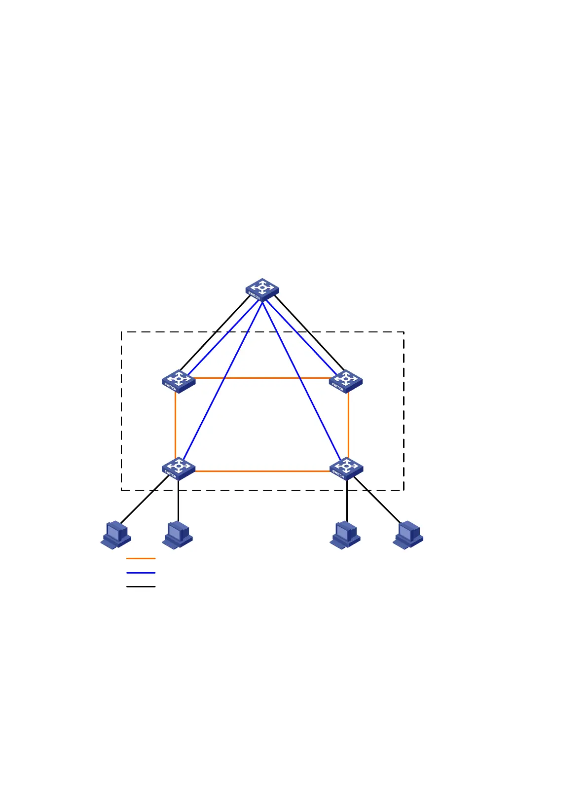
Figure 17 Network diagram
Device A
Device B
IRF
XGE1/3/0/2
(IRF-port1/2)
XGE3/2/0/1
(IRF-port3/1)
XGE3/2/0/2
(IRF-port3/2)
XGE4/2/0/1
(IRF-port4/1)
XGE4/2/0/2
(IRF-port4/2)
XGE2/2/0/1
(IRF-port2/1)
Device C Device D
GE1/2/0/1 GE2/3/0/1
XGE1/3/0/1
(IRF-port1/1)
XGE2/2/0/2
(IRF-port2/2)
GE3/3/0/1 GE4/3/0/1
IRF link
BFD link
Data link
GE1/0/1
GE1/0/2
GE1/0/3 GE1/0/4
Configuration considerations
• Device A is located at the distribution layer of the network. To improve the forwarding capability at
this layer, you must add three devices. In this example, Device B, Device C, and Device D are
added.
• To address the requirements for high availability, scalability, and ease of management and
maintenance, use IRF2 technology to create an IRF fabric with four member switches at the
distribution layer.