42
Start to check configuration with next startup configuration file, please wait.
.........DONE!
This command will reboot the device. Continue? [Y/N]:y
#May 6 15:31:09:724 2010 HP DEVM/1/REBOOT:
Reboot device by command.
%May 6 15:31:09:734 2010 HP DEVM/5/SYSTEM_REBOOT: System is rebooting now.
# After device reboot, Device B re-joins the IRF fabric. You can use the display irf command to view the
topology information about the IRF fabric.
<Sysname> display irf topology
Topology Info
-------------------------------------------------------------------------
IRF-Port1 IRF-Port2
Switch Link neighbor Link neighbor Belong To
2 DOWN -- UP 1 00e0-fc0f-8c02
1 UP 2 DIS -- 00e0-fc0f-8c02
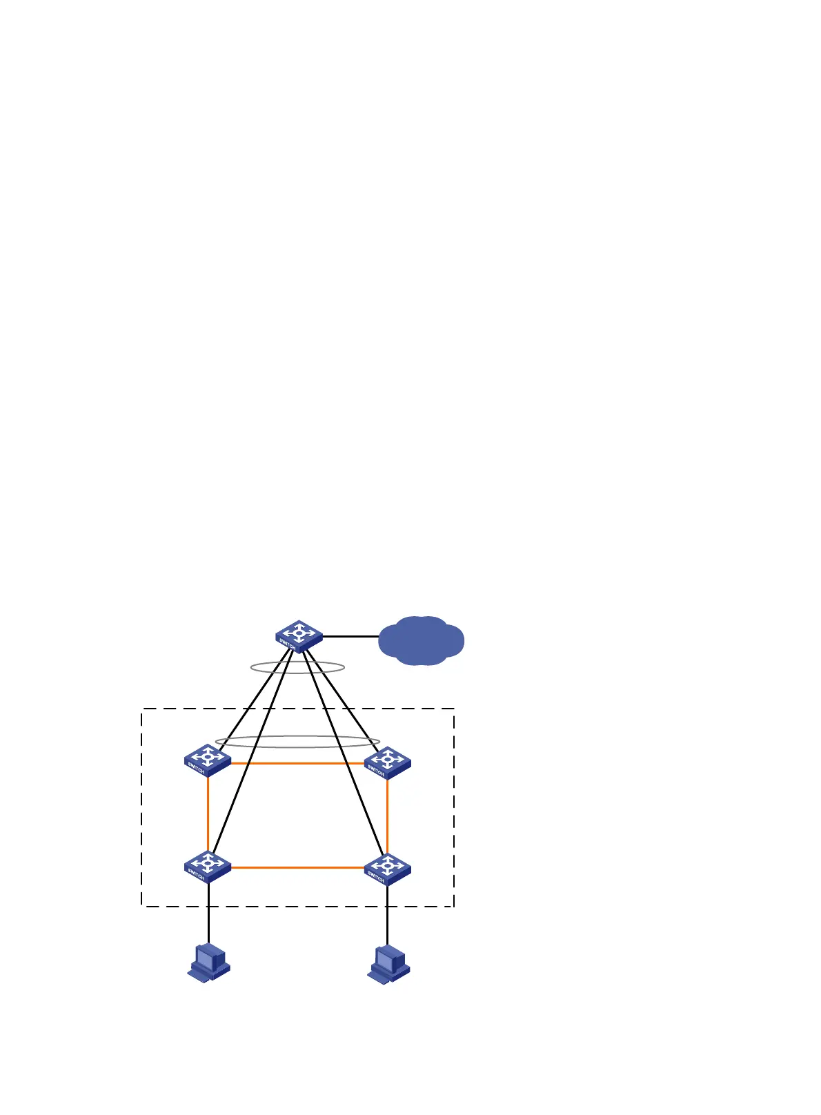
LACP MAD detection-enabled IRF configuration example (with
four member switches)
Network requirements
The number of PCs on the enterprise network (see Figure 16) is outgrowing the number of ports available
on the access switches. To address business growth, increase the number of ports at the access layer
while protecting the present investments of the customer and ensuring ease of management and
maintenance.
Figure 16 Network diagram
XGE1/3/0/1
(IRF-port1/2)
XGE2/3/0/2
(IRF-port2/1)
GE1/4/0/2
GE2/4/0/1
Device A
Device B
GE4/0/1
IRF
IP network
Device E
XGE1/3/0/2
(IRF-port1/1)
XGE2/3/0/1
(IRF-port2/2)
XGE3/2/0/2
(IRF-port3/2)
XGE3/2/0/1
(IRF-port3/1)
XGE4/2/0/2
(IRF-port4/2)
XGE4/2/0/1
(IRF-port4/1)
Device C Device D
GE3/3/0/1
GE4/3/0/1
GE4/0/2
GE4/0/3
GE4/0/4