Technical Reference Guide www.hp.com 2-15
System Overview
NOTE:
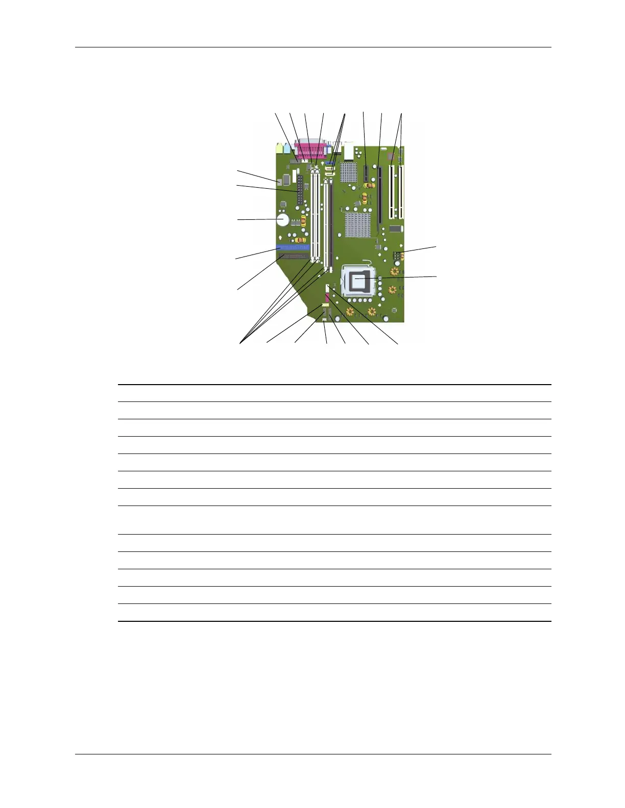
See SFF and ST rear chassis illustrations for externally accessible I/O connectors.
Figure 2-11. SFF/ST System Board
Item Description Item Description
1 Serial port header 13 Power button, power LED, HD LED header
2 Hood sense header 14 Chassis speaker connector
3 Password clear jumper 15 Front panel audio header
4 CMOS clear button 16 Front panel USB port connector
5 SATA #0 (blue), 1 (white), 2 (white) 17 DIMM sockets (4)
6 PCI Express x1 slot 18 Diskette drive connector
7 PCI Express x16 graphics/reversed-layout
SDVO slot
19 IDE (PATA) connector
8PCI 2.3 slots 20Battery
9 Power supply (VccP) connector 21 Power supply connector
10 Processor socket 22 Hood lock header
11 Processor fan connector
12 Chassis fan conenctor -- --
1
q
2
3
4
5
6
7
8
-
9
w
r
e
t
y
u
i
p
o
a
s
d
f
 Loading...