2-16 www.hp.com Technical Reference Guide
System Overview
NOTES:
See CMT rear chassis illustration for externally accessible I/O connectors.
[1] Applicable to CMT chassis only.
[2] Not included on MT system boards.
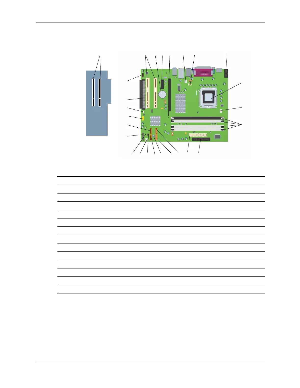
Figure 2-12. MT and CMT System Board and CMT PCI Expansion Board
Item Description Item Description
1 PCI 2.3 slots 14 SATA #3 connector
2 Battery 15 CMOS clear switch
3 PCI Express x1 slot 16 SATA #0 connector
4 PCI Express x16 graphics 17 Hood lock header
5 Chassis fan header 18 Hood sense header
6 Power supply (VccP) connector 19 Password clear jumper header
7 Serial port B header 20 Power LED/button, HD LED header
8 Processor socket 21 SATA #1 connector
9 Processor fan connector 22 Front panel USB port connector
10 DIMM sockets (4) 23 Internal speaker connector
11 Diskette drive connector 24 PCI expansion board connector [2]
12 Power supply connector 25 Front panel audio connector
13 SATA #2 connector -- --
1
q
2
3
4
5
6
7
8
-
9
w
e
d
f
g
z
j
k
l
r
t
y
u
i
p
o
a
s
System Board
PCI Expansion Board [1]
1