2–2 HP Integrity rx2600 server and HP workstation zx6000 Operation and Maintenance Guide
Installing or Replacing Parts and Accessories
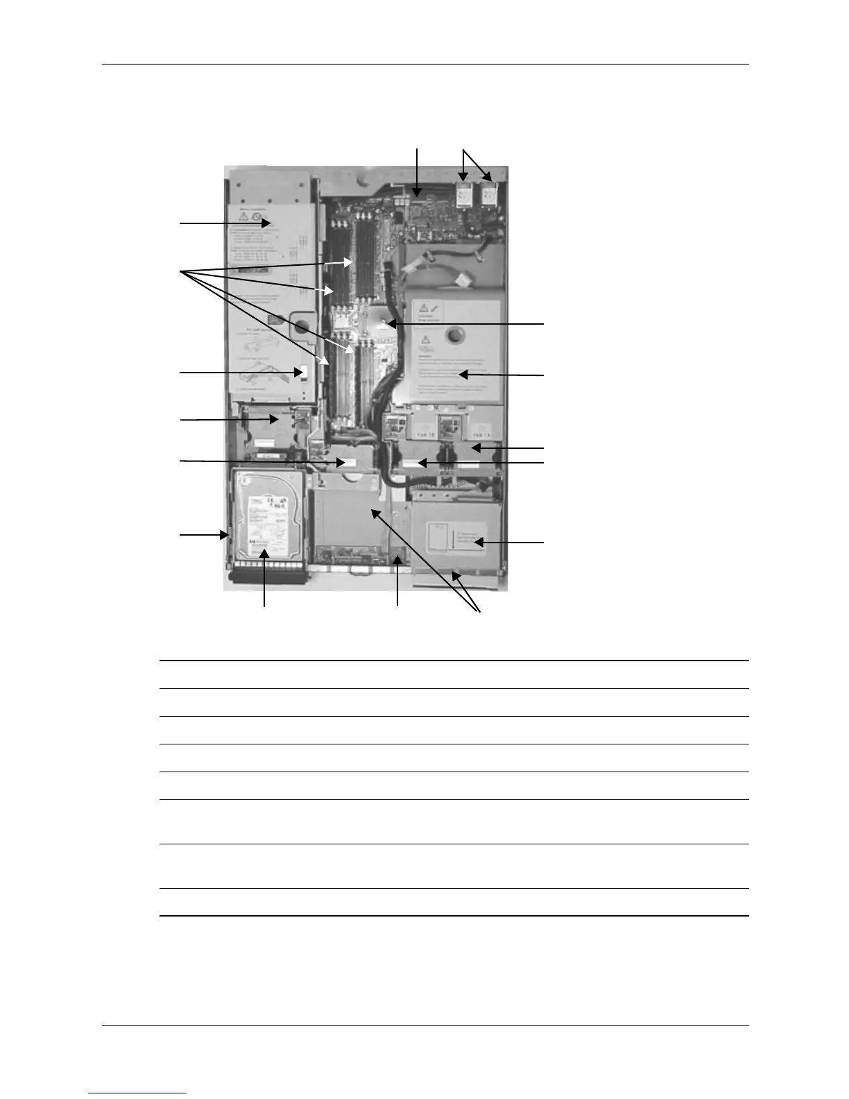
Location of Internal Components and Connectors
Internal Physical Layout (front of system at bottom of photo)
7
8
6
3
5
4
2
13
12
14
11
9
10
1 Power receptacles (PWR1 left, PWR2 right) 9 Hard disk lock
2 HP ZX1 memory and I/O controller 10 Memory fan(s)
3 Airflow guide 11 PCI fan
4 System fans (1A right, 1B left) 12 Intrusion switch
5 Slimline optical drive 13 Memory slots
6 Power supplies
(PSU1 center, PSU2 under optical drive)
14 PCI/AGP cage
7 Status panel board 15 Management Processor (MP) card
(optional)
8 Hot-swappable hard drives (up to 3)