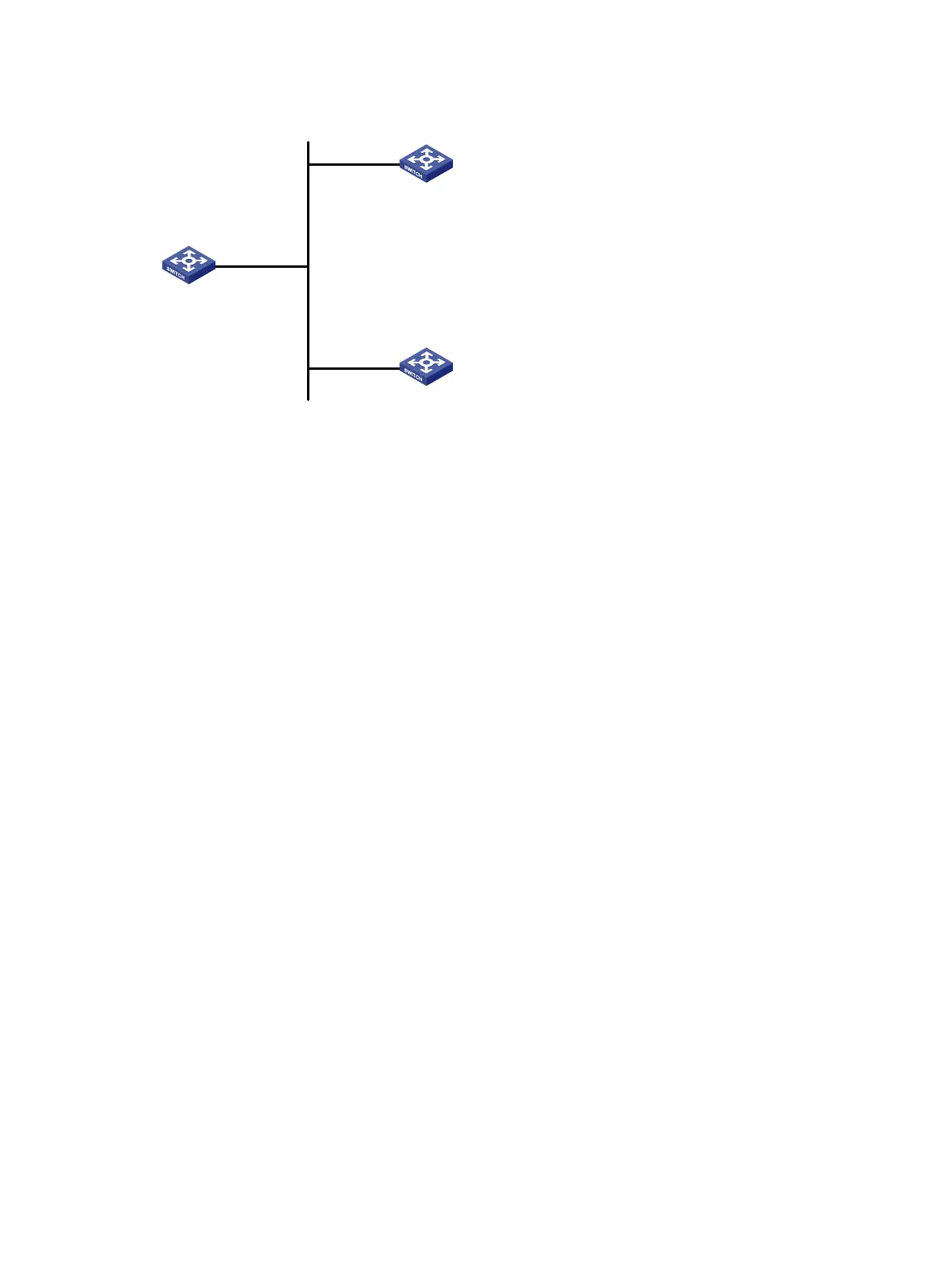
Figure 25 Network diagram for NTP broadcast mode configuration
Vlan-int2
3.0.1.31/24
Vlan-int2
3.0.1.32/24
Vlan-int2
3.0.1.30/24
Switch A
Switch C
Switch B
Configuration procedure
1. Set the IP address for each interface as shown in Figure 25. (Details not shown)
2. Configuration on Switch C:
# Configure Switch C to work in broadcast server mode and send broadcast messages through
VLAN-interface 2.
[SwitchC] interface vlan-interface 2
[SwitchC-Vlan-interface2] ntp-service broadcast-server
3. Configuration on Switch A:
# Configure Switch A to work in broadcast client mode and receive broadcast messages on
VLAN-interface 2.
<SwitchA> system-view
[SwitchA] interface vlan-interface 2
[SwitchA-Vlan-interface2] ntp-service broadcast-client
4. Configuration on Switch B:
# Configure Switch B to work in broadcast client mode and receive broadcast messages on
VLAN-interface 2.
<SwitchB> system-view
[SwitchB] interface vlan-interface 2
[SwitchB-Vlan-interface2] ntp-service broadcast-client
Switch A and Switch B get synchronized upon receiving a broadcast message from Switch C.
# Take Switch A as an example. View the NTP status of Switch A after clock synchronization.
[SwitchA-Vlan-interface2] display ntp-service status
Clock status: synchronized
Clock stratum: 3
Reference clock ID: 3.0.1.31
Nominal frequency: 64.0000 Hz
Actual frequency: 64.0000 Hz
Clock precision: 2^7
Clock offset: 0.0000 ms
Root delay: 31.00 ms
Root dispersion: 8.31 ms
65