21
13) Place the new component on the PCB. Be sure that it matches the PCB footprint.
14) Solder the new component.
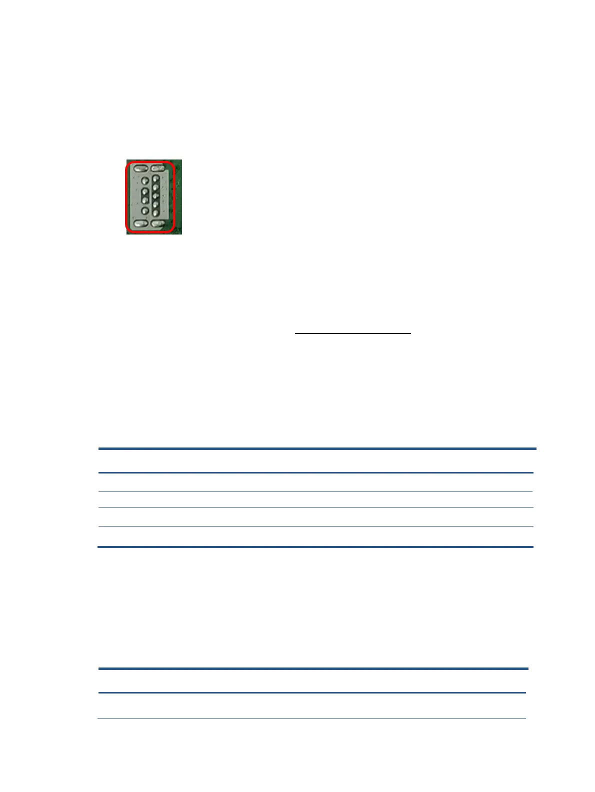
USB Type A connector UP2/UP3
Repair the USB Type A connector:
15) Use a soldering iron and a de-soldering pump to remove as much solder as possible from the pin.
16) Lift the UP2/UP3 connector from the PCB.
17) Place the new component on the PCB. Be sure that it matches the PCB footprint.
Solder the new component.
Before repairing connectors, follow these steps:
▲ Prepare the monitor for disassembly. See Preparation for disassembly on page 12.
Function test
After repair, be sure to confirm that all functions are working.
Support and troubleshooting
The following table lists possible problems, the possible cause or each problem, and the recommended
solutions.
Function test
After repair, be sure to confirm that all functions are working.
Table 4-1: Function test
Te
Operating description Tool used
VGA test Confirm whether image displays and sound plays
Computer or DVD player
Hub test Confirm whether data read correctly Computer or NB
Test item Operating description Tool used
HDMI test Confirm whether image displays and sound plays
Computer or DVD player
Type C test
Computer or DVD player
Table 4-2: Solving common problems
Problem Possible cause Solution
Screen is blank or
video is flashing.
Power cord is disconnected. Connect the power cord.
Confirm whether image displays and sound plays