ii
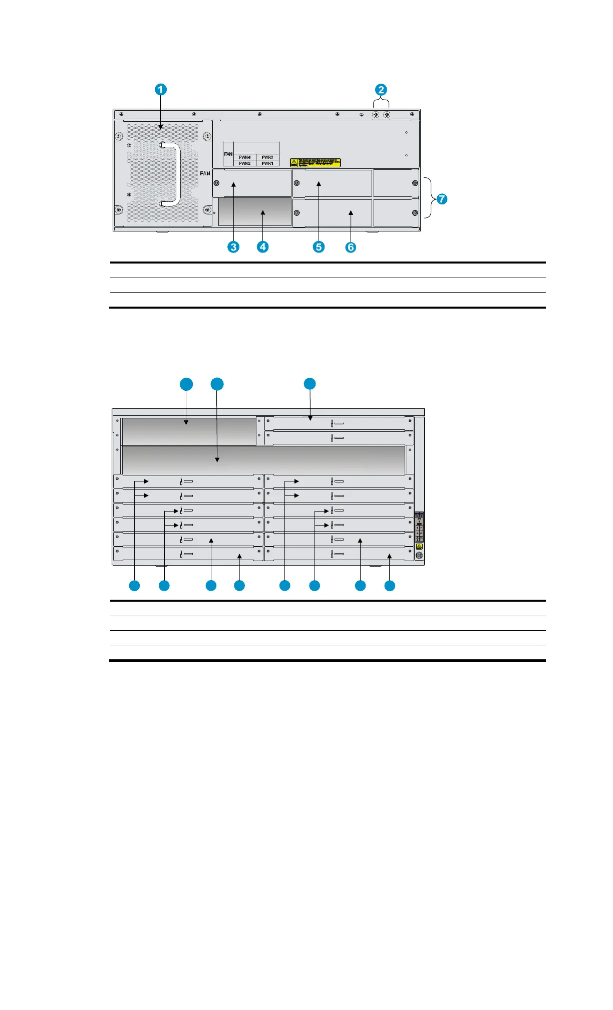
Figure 54 Rear view of the MSR4060
(1) Fan tray (2) Grounding terminal (3) Power module slot PWR4
(4) Power module slot PWR2 (5)
Power module slot PWR3 (6)
Power module slot PWR1
(7) Filler panels of the PoE power module slots
MSR4080
Figure 55 Front view of the MSR4080
(1) MPU slot 0 (2) SPU slot (3) MPU slot 1
(4) HMIM slot 8 (5)
HMIM slot 6 (6)
HMIM slot 4
(7) HMIM slot 2 (8)
HMIM slot 7 (9)
HMIM slot 5
(10) HMIM slot 3 (11) HMIM slot 1
1
2
3
5
7
10
11
6 8
9
4

 Loading...


