iv
Appearance of SPUs
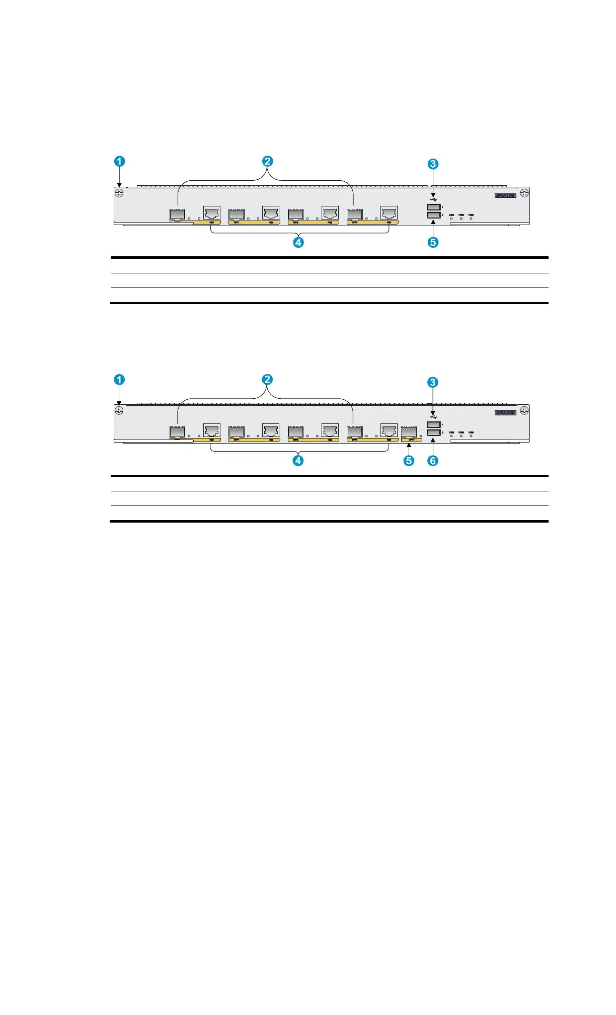
SPU-100
Figure 58 Rear view of the SPU-100
(1) Captive screw (2) Fiber Ethernet ports SFP0 through SFP3
(3) USB port 1 (4)
Copper Ethernet ports GE0 throu
h GE3
(5) USB port 0
SPU-200
Figure 59 Rear view of the SPU-200
(1) Captive screw (2) Fiber Ethernet ports SFP0 through SFP3
(3) USB port 1 (4)
Copper Ethernet ports GE0 throu
h GE3
(5) SFP+ port (6)
USB port
0
Appearance of power modules
You can configure one or two power modules for the MSR4000 routers. The power modules are
hot-swappable. You can replace a faulty power module if the other power module can provide all
required system power.
To configure one power module, install the AC or DC power module to any of the PWR1 through
PWR4 slots.
To configure two power modules for redundancy, install two AC power modules or two DC power
modules to any of the PWR1 through PWR4 slots. Do not install an AC and a DC power module on
the same router.
When the router is installed with an interface module that supports PoE, and needs to supply power to
powered devices (PDs), install a PoE power module to the router.

 Loading...


