iii
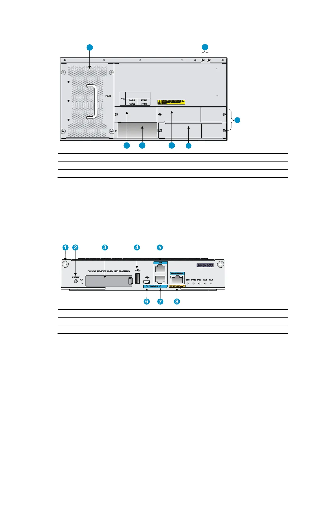
Figure 56 Rear view of the MSR4080
(1) Fan tray (2)
Groundin
terminal (3)
Power module slot PWR 4
(4) Power module slot PWR 2 (5) Power module slot PWR 3 (6) Power module slot PWR1
(7) Filler panels of the PoE power module slots
Appearance of the MPU
MPU-100 is required for the MSR4000, which performs protocol processing, low-speed packet
forwarding, interface control, and fault detection. The MPU runs system programs and saves
configuration information of the router.
Figure 57 Front view of the MPU-100
(1) Captive screw (2)
Reset button (3)
CF card slot
(4) USB port (5) AUX port (6) USB console port
(7) Console port (8)
Mana
ement Ethernet port
1
2
4
3
5
6
7

 Loading...


