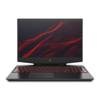
4. Slide the module horizontally out of the socket and slightly under the heat sink (4), and then slide the
module over the socket and out from under the heat sink (5).
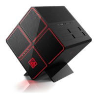
5. If the WLAN antenna is not connected to the terminal on the WLAN module, install a protective sleeve on
the antenna connector, as shown in the following illustration.
To install the WLAN module, reverse this procedure.
Speakers
To remove the speakers, use this procedure and illustration.
Table 6-4
Speaker description and part number
Description Spare part number
Speaker Kit N14088-001
Before removing thespeakers, follow these steps:
40
Chapter 6Removal and replacement procedures for authorized service provider parts
 Loading...