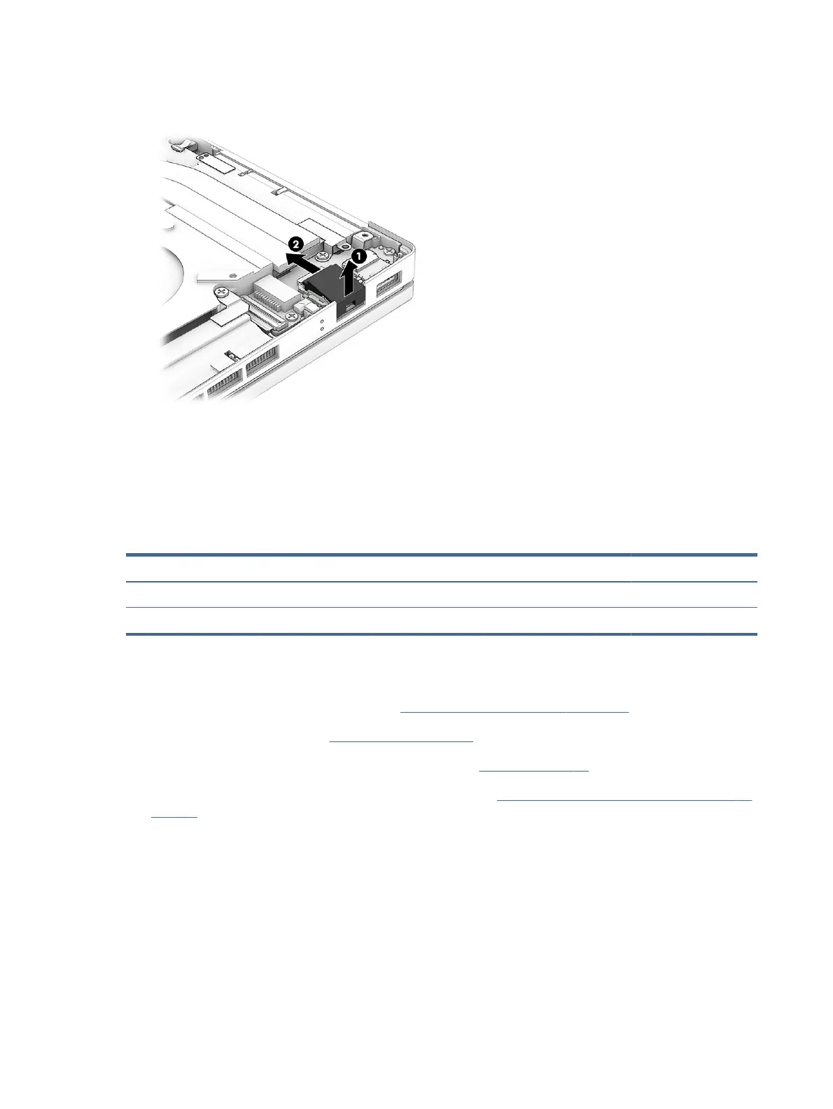
4. If you need to remove the RJ-45 (network) door, insert a tool into the outside of the door (1) and push
the door upward to release it (2).
To install the RJ-45 (network) board, reverse this procedure.
USB board
To remove the USB board, use this procedure and illustration. Before removing the board, you can remove the
system board, heat sink, and fans as an assembly so you do not have to disturb the thermal material.
Table 6-11
USB board description and part number
Description Spare part number
USB board N14063-001
USB board cable N14064-001
Before removing the USB board, follow these steps:
1. Prepare the computer for disassembly (see Preparation for disassembly on page 36).
2. Remove the bottom cover (see Bottom cover on page 36).
3. Disconnect the battery cable from the system board (see Battery on page 37).
4. Remove the system board, heat sink, and fan assembly (see System board, heat sink, fan combination on
page 48).
Remove the USB board:
1. Disconnect the cable from the ZIF connector on the USB board (1).
2. Remove the two Phillips M2.0 × 3.5 screws (2) that secure the board to the computer.
52
Chapter 6Removal and replacement procedures for authorized service provider parts
 Loading...