2. Remove the bottom cover (see Bottom cover on page 36).
3. Disconnect the battery cable from the system board (see Battery on page 37).
4. Remove the heat sink (see Heat sink assembly on page 46).
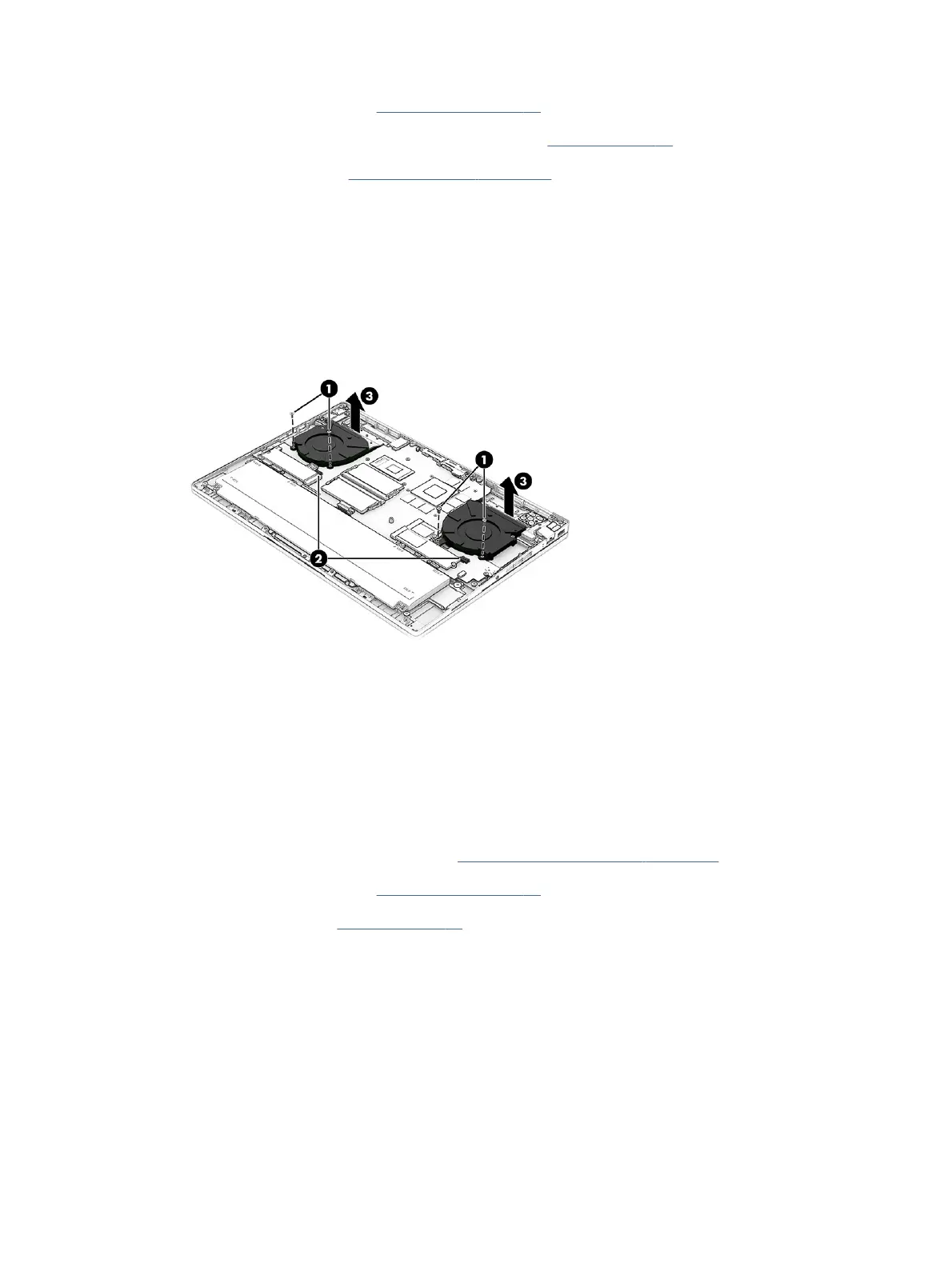
Remove the fans:
1. Remove the two Phillips M2.0 × 5.0 screws (1) that secure each fan to the computer.
2. Remove the protective Mylar, and then disconnect the fan cables from the system board (2).
3. Remove the fans (3).
To install the fans, reverse this procedure.
System board, heat sink, fan combination
If you remove the RJ-45 board, USB board, touchpad, IR sensor board, and display assembly, you can remove
the system board, heat sink, and fans together to avoid removing the heat sink and disturbing the thermal
material.
Before removing thesystem board, heat sink, and fan assembly, follow these steps:
1. Prepare the computer for disassembly (see Preparation for disassembly on page 36).
2. Remove the bottom cover (see Bottom cover on page 36).
3. Remove the battery (see Battery on page 37).
Remove the system board, heat sink, and fan assembly:
1. Disconnect the following cables from the system board:
● Display cable (1)
● Sensor board cable (ZIF) (2)
● RJ-45 (network) board cable (ZIF) from the RJ-45 board (3)
● Wireless antenna cables from the WLAN module (4)
48
Chapter 6Removal and replacement procedures for authorized service provider parts
 Loading...