apply thermal gel are noted by small square brackets in white on the board. (3) Reinstall the
thermal module onto the system board.
Reverse this procedure to install the heat sink.
Power connector cable
To remove the power connector cable, use this procedure and illustration.
Table 5-9 Power connector cable description and part number
Description Spare part number
Power connector cable M57115-001
Before removing the power connector cable, follow these steps:
1. Prepare the computer for disassembly (see Preparation for disassembly on page 29).
2. Remove the bottom cover (see Bottom cover on page 29).
3. Disconnect the battery cable from the system board (see Battery on page 30).
4. Remove the heat sink (see Heat sink on page 38).
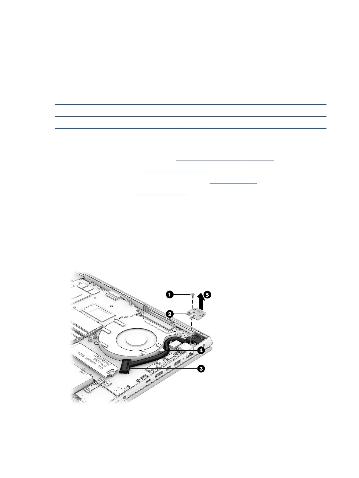
Remove the power connector cable:
1. Remove the Phillips M2.0 × 5.0 screw (1) from the power connector bracket.
2. Remove the bracket (2).
3. Disconnect the cable from the system board (3).
4. Remove the cable from the clip on the side of the fan (4).
5. Remove the power connector cable from the computer (5).
Reverse this procedure to install the power connector cable.
40 Chapter 5 Removal and replacement procedures for authorized service provider parts