EasyManuals Logo

HP P6000 Installation Guide

HP P6000
74 pages
To Next Page IconTo Next Page
To Previous Page IconTo Previous Page
Page #70 background imageLoading...
Page #70 background image
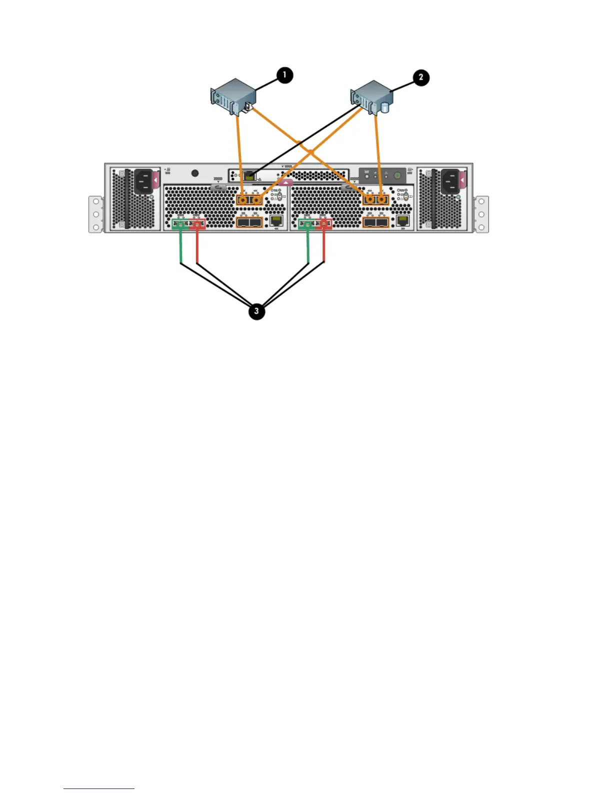
Figure 59 Cabling the controller to front end component—direct Fibre Channel to servers with
array-based management
1. File server
2. Database server
3. Indicates cabling connections to disk enclosures. See Figure 51 (page 62) and Figure 55 (page 66) for cabling
connections.
iSCSI and iSCSI/FCoE
You can connect the front of the P6300/P6500 EVA iSCSI or iSCSI/FCoE controllers to Ethernet,
SAN, or FCoE switches as shown in the following diagrams. Connections shown in orange indicate
1 GbE, blue connections indicate 8 Gb/s FC, and black connections indicate Ethernet management.
70 Cabling the P6300/P6500 EVA

Table of Contents

Other manuals for HP P6000

Questions and Answers:

Question and Answer IconNeed help?

Do you have a question about the HP P6000 and is the answer not in the manual?

HP P6000 Specifications

General IconGeneral
RAID Levels Supported0, 1, 5, 6, 10
Form FactorRack-mountable
Hard Drive Form Factor2.5", 3.5"
Drive Types SupportedSAS, SSD, SATA
RedundancyRedundant power supplies
Host ConnectivityFibre Channel, iSCSI
Operating Temperature10° to 35°C (50° to 95°F)

Related product manuals