14
The HP ProCurve Switch 8200zl series requires at least a single management module that oversees (or
“supervises”) the operation of the interface modules and fabric modules. The management module is
responsible for network control processing (e.g., OSPF updates or ARP requests), while each interface module
in conjunction with the fabric modules handles the traffic switching in ASIC hardware.
The use of dual management modules by default synchronizes configuration information and code images
automatically for the user. There is no need for a “synchronize” command. When configuration changes are
written to flash memory (“write memory”) or software updates are performed on the Active Module (a TFTP
copy of newer software into Flash), they are automatically copied over to the Standby Management Module.
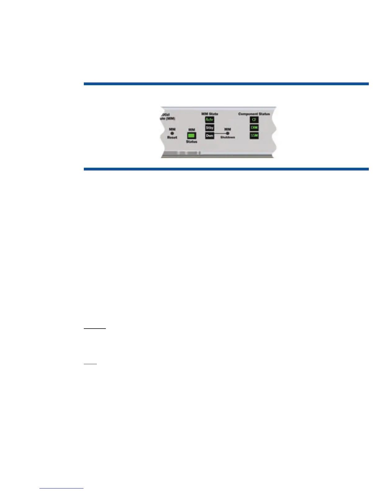
Figure 4. Close-up of the Management Module LEDs in a typical operational state
The LEDs on the 8200zl Management Module are grouped in two columns:
•Onesettoindicatethemanagementmodule’s“state”(Active,Standby,orDown)
•Onesettoindicatethestatusofcomponents(CompactFlashandDIMMsystemmemory)andcommunication
status with the System Support Module (SSM)
The “MM Status” LED indicates general health of the management module, indicated by a green color
after the module has passed power on self-test. “MM Reset” is a recessed button used to manually reset the
management module. The management modules are designed to be hot-swappable and can be removed
from the chassis without damage. The synchronization of files (configuration, code images, state, and default
condition directives) may indeed be occurring; so to minimize the possibility of corruption between MMs, when
manually removing the module, use the “MM Shutdown” button. “MM Shutdown” is a recessed button used to
gracefully shut down the management module, completing any synchronization of files and state information to
the second management module. When the “Down” LED is lit, the management module can be removed. The
LED indicators are covered in more detail in “Appendix K: Troubleshooting” later in this document.
Processor
The CPU processor is a Freescale PowerPC 8540 operating at 667 MHz.
Memory
SDRAM
Synchronous Dynamic RAM is used for the storage of uncompressed executable code and data structures. The
SDRAM consists of a 256 MB DDR-1 DIMM in the base module, expandable up to 1 GB. The DDR-1 interface
is 64 bits running at 166 MHz bus speed (333 MHz data rate).
Flash
The flash consists of a 128 MB CompactFlash, expandable up to 1 GB, and a 4 MB mirror-bit flash. The mirror-
bit flash is used for initial boot code. The CompactFlash is used for nonvolatile configuration storage and
compressed code storage. The CompactFlash is socketed for future upgrade capability.
The CompactFlash may be programmed in a bulk fashion or one sector at a time. Because all application
code is executed out of SDRAM, the CompactFlash may be programmed while the switch is operational; in
other words, you can download new code onto the CompactFlash during system operation. The CompactFlash
is sized so that a backup copy of an older revision of application code also may be stored. The system also
allows you to hold up to three copies of configuration files, associating them to a particular flash image
(primary = Config1, secondary = Config2, Active Running session = Config3).

 Loading...