23
5406zl chassis layout
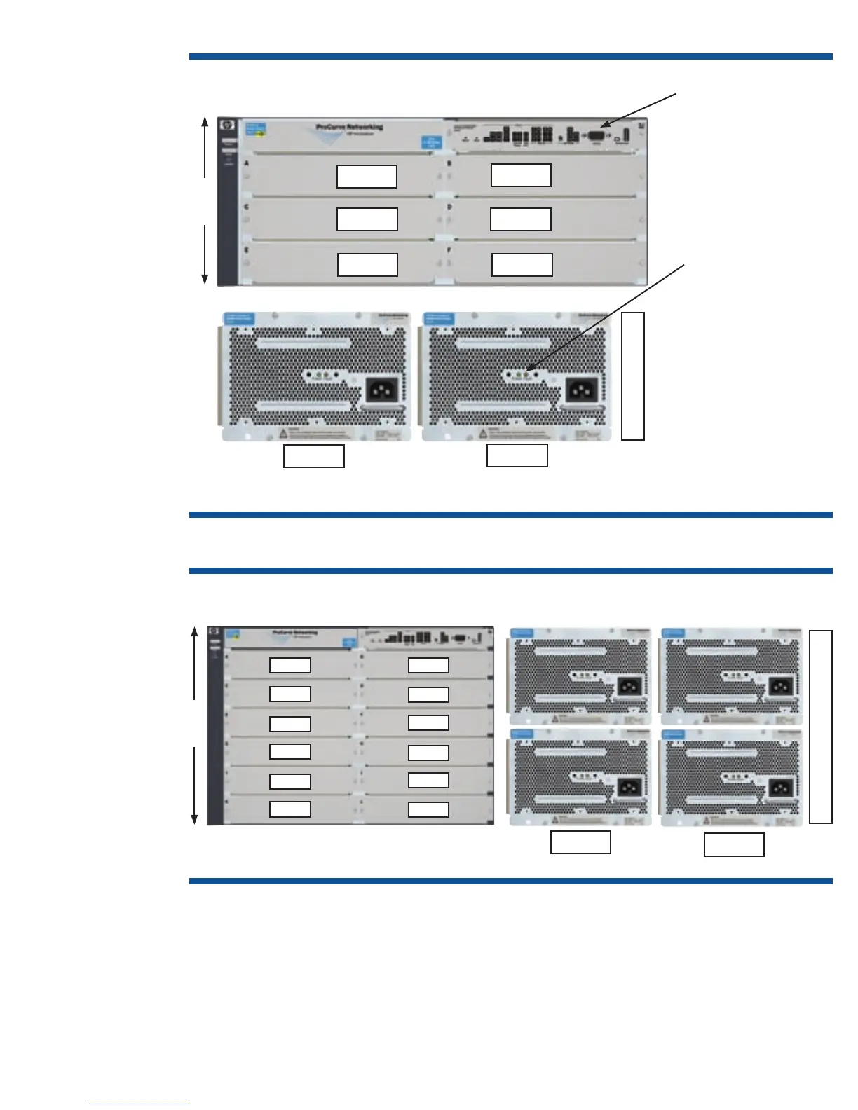
Figure 12. HP ProCurve Switch 5406zl chassis layout
Figure 13. HP ProCurve Switch 5412zl chassis layout
5412zl chassis layout
The internal power supplies are inserted in the back slots. These slots are labeled PS1 and PS2 on the 5406zl
and PS1 through PS4 on the 5412zl. A power supply is hot-swappable provided at least one other power
supply is operational. If the 5412zl has only two power supplies and one of them fails, then only the upper six
slots (slots A through F) will receive power.
Front
Slot A
Slot C
Slot E
Slot B
Slot D
Slot F
Back
Management module
and its cflash and battery
are customer removable/
replaceable
4U
EPS 2
EPS 1
Fan Tray
Power and Fault
indicators
Power supply
is hot-swappable *
Fan tray is hot-swappable;
however, auto-shutdown
commences if not
replaced within
3 minutes
PS1
PS2
* Provided a second power supply remains operational
Slot A
Slot C
Slot E
Slot G
Slot I
Slot K
Slot B
Slot D
Slot F
Slot H
Slot J
Slot L
Front
Back
PS3
PS1
PS4
PS2
Fan Tray
EPS 2
EPS 1
7U

 Loading...