Limitations/Restrictions
•MeshingandDistributedTrunkingfeaturesaremutuallyexclusive.
•RoutingandDistributedTrunkingfeaturesaremutuallyexclusive.
•IGMPandDHCPsnooping,ARP-protect,andSTParenotsupportedonDTtrunks.
•Q-in-QinmixedVLANmodeandDTaremutuallyexclusive.
•ISCportswillbepartofallVLANs—i.e.,theywillbecomemembersofaVLANoncethatVLANisconfigured.
•ISCportcanbeanindividualportoramanualLACPtrunk,butadynamicLACPtrunkcan’tbeconfiguredas
an ISC port.
•Maximumof8linksinaDTtrunkacrosstwoswitchesissupportedwithamaximumof4linksperDTswitch.
•Thecurrentlimitationof60manualtrunksinaswitchwillnowincludeDTmanualtrunkstoo.
•OneISCissupportedperswitchforamaximumof60DTtrunkssupportedintheswitch.
•SpanningTreeProtocolisdisabled(i.e.,PDUsarefiltered)onDTports.
An example of upstream traffic forwarding is as follows
Assuming the uplink connected to Switch B is blocked by STP and only an uplink in Switch A is active. Server 1
sent traffic with load-balance across its 802.3ad LACP links. If the receiving switch is Switch A, which learns the
destination MAC from any of the upstream links, it will forward the unicast frames to destination directly via its
upstream link. If Switch B receives the unicast frame from the server and it learns DA (destination address) MAC
from Switch A, Switch B will forward the frames to Switch A, and in turn Switch A forwards the frames to the
destination via its upstream link. Thus, unicast frames are always forwarded by only one of the DT switches.
Appendix K: Troubleshooting
LED status indicators for Switch 8200zl series
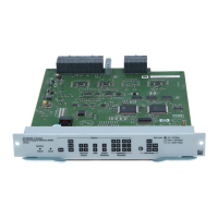
The HP ProCurve Switch 8200zl Management Module has various LED status indicators that are described in
Table A1.
Table A1: LED status indicators for management/system support module
LED State Indication
Power On (green) The switch is receiving power.
Off The switch is NOT receiving power.
Fault On (orange) On briefly at the beginning of switch self-test, after the switch is powered on or reset. If on for a
prolonged time, the switch has encountered a fatal hardware failure, or has failed its self-test.
Off The normal state; indicates there are no fault conditions on the switch.
Blinking (orange) A fault has occurred on the switch, one of the switch modules, an individual port, a power supply, or
a fan. The Status LED for the module or other device with the fault will flash simultaneously.
Test On (green) The switch self-test and initialization are in progress after you have power-cycled or reset the switch.
The switch is not operational until this LED goes off. The Self-Test LED also comes on briefly when you
“hot-swap” a module into the switch and the module is automatically self-tested.
Off Normal operation; the switch is not undergoing self-test.
Blinking (orange) A component of the switch has failed its self-test. The Status LED for that component—for example, a
switch module—and the switch Fault LED will flash simultaneously.
DIMM
(marked as “DIM”)
Dual-Inline Memory
Module on the
Management
Module
On (green) Normal operation.
Off DIMM status is unknown.
Blinking (orange) If DIMM, Fault, and Self-Test LEDs are blinking, DIMM failed self-test. If DIMM and Fault LEDs are
blinking, an operational fault has occurred. If blinking at a fast rate, an operational alert occurred
and is unresolved.
Flash On (green) Flash Card status is known and fault-free.
Off Flash Card status is unknown.
Blinking (orange) If Flash, Fault, and Self-Test LEDs are blinking, Flash Card failed self-test.
If Flash and Fault LEDs are blinking, an operational fault has occurred.
If blinking at a fast rate, an operational alert occurred and is unresolved. For example, Flash Card is
not present.
71
 Loading...


