Connectors, Switches, and LED Indicators
System Board Connectors
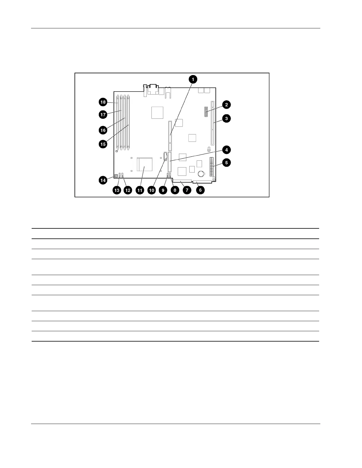
The following figure and table show system board connectors on the system board.
Figure 4-3: System board connectors
Table 4-3: System Board Connectors
Item Description Item Description
1 Slotless SCSI module connector (option) 10 Remote Insight Lights-Out Edition II connector
2 System configuration switch (SW4) 11 Processor socket (populated)
3 64-bit 33-MHz PCI riser board assembly
connector
12 Fan 3 connector
4 ATA controller (secondary) 13 Fan 4 connector
5 Power supply connector 14 Processor power connector
6 Optical device/diskette drive assembly cable
connector
15 DIMM socket 1
7 ATA controller (primary) 16 DIMM socket 2
8 Fan 1 connector 17 DIMM socket 3
9 Fan 2 connector 18 DIMM socket 4 (populated)
4-4 HP ProLiant DL320 Generation 2 Server Maintenance and Service Guide
 Loading...