Do you have a question about the HP PROLIANT DL320 G6 and is the answer not in the manual?
Explains HP's parts-only warranty service, providing replacement parts free of charge.
Lists and illustrates various server components available as parts.
Lists necessary tools for performing server maintenance and replacement tasks.
Provides essential safety information and precautions before performing service procedures.
Details precautions to prevent damage from static electricity during handling of components.
Explains symbols used on equipment to indicate hazardous conditions.
Alerts users to safety precautions and potential hazards when working with racks.
Highlights important warnings and cautions related to server operation and handling.
Outlines the necessary preparation steps before performing service procedures.
Step-by-step guide on how to safely power down the server before servicing.
Instructions for safely removing the server from its rack mounting.
Details the removal and replacement of a hard drive blank or bay filler.
Provides instructions for removing and replacing server hard drives.
Describes how to remove and replace the server's access panel for component access.
Instructions for removing and replacing the air baffle for proper cooling.
Step-by-step guide for removing and replacing redundant hot-plug power supplies.
Details the procedure for removing and replacing the redundant hot-plug power supply cage.
Instructions for removing and replacing a 460-W pluggable AC power supply.
Procedure for removing and replacing the 460-W pluggable AC power supply backplane.
Steps for removing and replacing the non-hot-plug power supply bracket.
Instructions for removing and replacing a non-hot-plug power supply.
Step-by-step guide for removing and replacing a server fan.
Instructions for removing and replacing a fan clip.
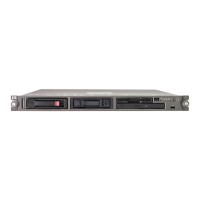
Procedure for removing and replacing the server's optical drive.
Steps to remove and replace the hard drive cage assembly.
Procedure for removing and replacing the SAS/SATA backplane.
Instructions for removing and replacing the PCI riser board assembly.
Procedure for removing and replacing an expansion board.
Outlines procedures for battery-backed write cache (BBWC) options.
Steps for removing and replacing the cache module for BBWC.
Instructions for removing and replacing the cache battery.
Procedure for recovering data from a failed battery-backed write cache.
Outlines procedures for flash-backed write cache (FBWC) options.
Steps for removing and replacing the flash-backed write cache module.
Instructions for removing and replacing the FBWC capacitor pack.
Procedure for removing and replacing the dedicated iLO 2 connector module.
Steps for removing and replacing DIMM memory modules.
Instructions for removing and replacing the processor heatsink.
Step-by-step guide for removing and replacing the server processor.
Instructions for removing and replacing the system board.
Procedure for removing and replacing the system board battery.
Information about the HP Trusted Platform Module and its non-customer-removable status.
Lists resources and guides for troubleshooting server issues.
Details the HP Insight Diagnostics tool for system verification and repair.
Explains the survey functionality of HP Insight Diagnostics for gathering system information.
Describes the Integrated Management Log (IML) for recording system events.
Information on HP Insight Remote Support software for enhanced product support.
Details the USB 2.0 and legacy USB support provided by the server.
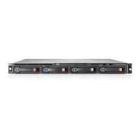
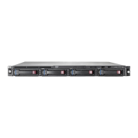
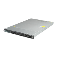
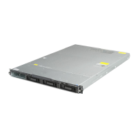
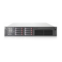
Identifies and illustrates components located on the front panel of the server.
Explains the function and status of front panel LEDs and buttons.
Describes combinations of system LEDs and internal health LEDs indicating system status.
Illustrates the numbering scheme for SAS and SATA devices.
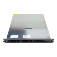
Identifies and illustrates components located on the rear panel of the server.
Explains the function and status of rear panel LEDs and buttons.
Defines the specifications and types of PCI expansion slots.
Identifies and labels various components and connectors on the system board.
Details the positions and functions of the system maintenance switch.
Explains the Non-Maskable Interrupt (NMI) functionality for crash dump analysis.
Describes the system board LEDs and their corresponding statuses.
Shows the locations of fans within the server chassis.
Explains the status indicated by the LEDs on the FBWC module.
Provides guidelines for optimal server and hardware cabling.
Details how to route cables for non-redundant power supplies.
Guidelines for cabling optional non-redundant high-efficiency power supplies.
Instructions for cabling optional redundant power supplies.
Guidelines for cabling optional common slot power supplies.
Details the cabling for SATA drives.
Instructions for cabling optional SAS drives.
Cabling instructions for BBWC battery pack or FBWC capacitor pack.
Details the environmental operating conditions for the server.
Provides the mechanical dimensions and specifications of the server.
Lists the input and output specifications for various power supplies.
| Form Factor | 1U rack |
|---|---|
| Processor | Intel Xeon 3400 series |
| Memory Type | DDR3 |
| Maximum Memory | 32GB |
| Storage | Up to 4 LFF (3.5-inch) or 4 x 3.5" drives |
| Storage Controller | HP Smart Array P410 |
| Network | HP NC107i PCI Express Gigabit Server Adapter |
| Power Supply | 400W non-hot plug, non-redundant |
| Expansion Slots | 1 x PCIe x16 |