Do you have a question about the HP ProLiant DL580 Generation 2 and is the answer not in the manual?
Information on the intended audience for this maintenance and service guide.
Important safety and repair guidelines for trained service technicians.
Lists various HP resources for further technical assistance and documentation.
Explains the server's log for fault and management information.
Contact numbers for HP authorized resellers and technical support.
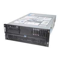
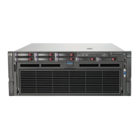
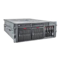
Visual representation of the server's external and mechanical components.
A list of spare part numbers for mechanical components.
Visual representation of the server's internal components.
A list of spare part numbers for internal system components.
Essential safety information and precautions before performing any service procedures.
Guidelines to prevent damage to electronic components from static electricity.
Explains various warning symbols found on the server equipment.
Safety guidelines for installing and handling the server in a rack.
Critical warnings and cautions for server operation and component handling.
Steps required before starting component removal or replacement.
Instructions for finding and using the Torx T-15 tool for screw removal.
Procedure to extend the server from its rack for easier access.
Steps to open and remove the server's rear access panel.
Steps to remove the server's front access panel.
Procedure for reinstalling the front and rear access panels.
Instructions on how to safely power down the server for maintenance.
Steps to safely remove the server from its rack mounting.
Information on memory components and installation/removal procedures.
Guidelines for replacing memory, including hot-plug support.
Identifies the physical locations of memory board slots on the system board.
Details the different components and connectors on a memory board.
Explains the status indicators and icons on the memory board.
Specific rules for installing DIMMs to ensure proper memory operation.
Configuration requirements for using online spare memory.
Configuration requirements for single-board mirrored memory.
Configuration requirements for hot-plug mirrored memory.
Step-by-step guide to remove a memory board from the server.
Procedure for removing a DIMM from a memory board.
Procedure for installing a DIMM into a memory slot.
Step-by-step guide to install a memory board into the server.
Steps to configure the server's memory settings via RBSU.
Procedures for replacing components without powering down the server.
Instructions for removing and replacing hard drive blanks.
Precautions and procedures for hot-plugging SCSI hard drives.
Instructions for removing and replacing a power supply blank.
Precautions and procedures for hot-plugging power supplies.
Procedures for handling PCI/PCI-X expansion boards with hot-plug capability.
Recommendations for optimal expansion board placement for performance.
Procedure for hot-plugging system fans.
Procedures for replacing components that require the server to be powered down.
Procedure for removing and replacing slimline drives.
Steps to remove and replace the front bezel of the server.
Procedure to remove and replace the power button and LED assembly.
Steps to remove and replace the processor air baffle.
Procedure to remove and replace Processor Power Modules (PPMs).
Detailed steps for removing and replacing server processors.
Procedure to remove non-hot-plug PCI-X expansion boards.
Steps to remove and replace the PCI-X expansion board basket.
Procedure for removing and replacing a PCI-X hot plug board.
Steps to disconnect and remove SCSI cables.
Procedure to remove and replace the front fan cage assembly.
Steps to remove the pass-through board.
Procedure to remove the removable media board.
Procedure to remove and replace the rear fan cage assembly.
Procedure to remove the Battery-Backed Write Cache assembly.
Steps to remove and replace the SCSI backplane.
Procedure for removing and replacing the system battery.
Detailed steps for removing and replacing the server system board.
Procedure to remove and replace the AC filter cable assembly.
Steps to re-enter the server's serial number after system board replacement.
Overview of software and firmware tools for server diagnostics and management.
Identification of rear panel, system board, SCSI backplane, and memory board connectors.
Explains various LEDs indicating component status across the server.
Details the four LEDs on the server's front panel and their status.
Explains diagnostic LEDs and interlock status indicators on the system board.
Describes LEDs for hot-plug drives, fans, and power supplies.
Explains LEDs for PCI-X slots and network interface controllers.
Details memory board LEDs and their statuses for different memory modes.
Explains the purpose and configuration of system board switches.
Describes System Maintenance (SW4) and System ID (SW7) switches.
Details iLO/Spread Spectrum (SW8) and NMI switches.
Describes the rear unit identification LED switch.
Systematic instructions for diagnosing problems when the server fails to start.
A series of questions to guide troubleshooting based on observed server symptoms.
Information for troubleshooting issues that occur after the initial boot process.
Procedure for recreating the ROM BIOS using disaster recovery mode.
Lists additional resources for troubleshooting and product information.
Detailed specifications for the HP ProLiant DL580 Generation 2 server.
| Processor Socket | Socket 604 |
|---|---|
| Storage Controller | Integrated Smart Array 6i Controller |
| Storage | SAS |
| Network | Integrated Dual Gigabit NICs |
| RAID Support | RAID 0, 1, 5 |
| Expansion Slots | 6 PCI-X slots |
| Power Supply | Redundant Power Supplies |
| Form Factor | 4U Rack |
| Management | HP Integrated Lights-Out (iLO) |
| Operating System Support | Windows Server, Linux |
| Processor | Intel Xeon (up to 4 processors) |
| Drive Bays | Up to 6 hot-plug SCSI or SAS drives |