Connectors, LEDs, and Switches
System Board
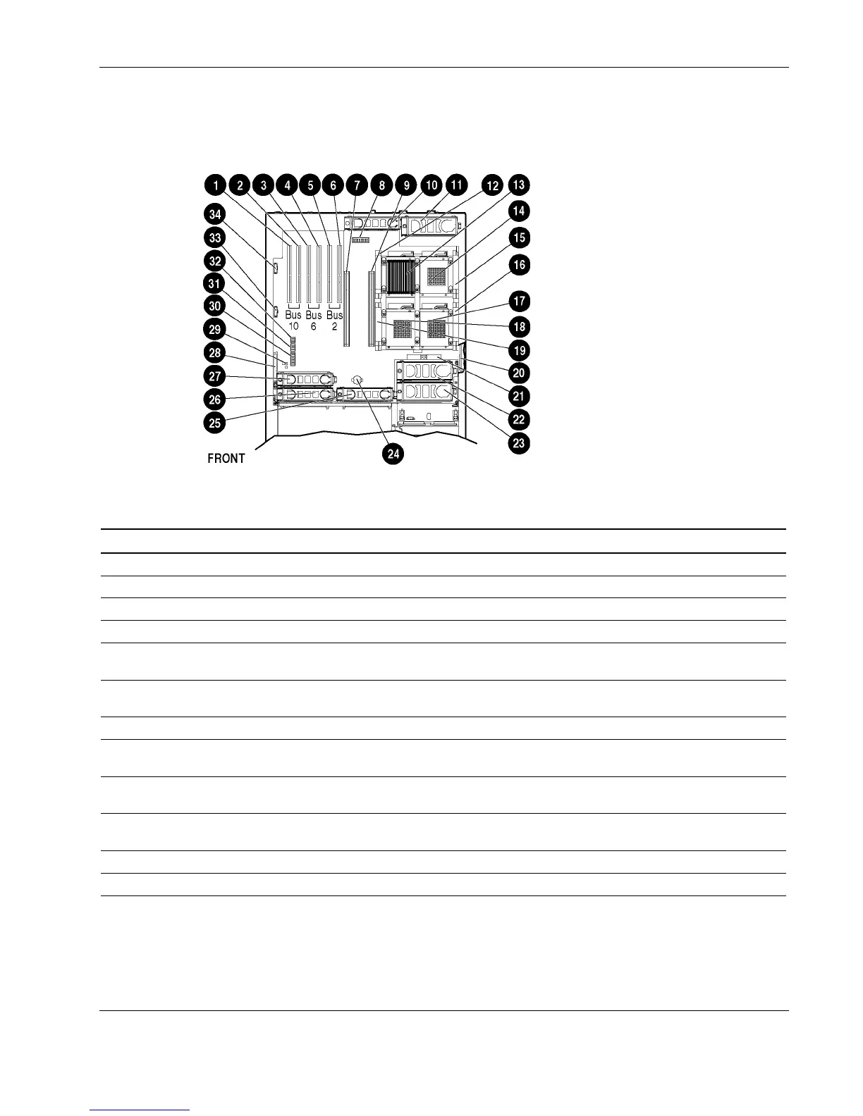
Figure 4-2 and Table 4-2 illustrate the connectors located on the system board.
Figure 4-2: System board connectors
Table 4-2: System Board Connectors
Item Description Item Description Item Description
1 Non-hot-plug expansion slot 1 13 Processor 1 25 Hot-plug fan 3
2 Non-hot-plug expansion slot 2 14 Processor socket 2 26 Hot-plug fan 1
3 Hot-plug slot 3 15 PPM slot 2 27 Hot-plug fan 2
4 Hot-plug slot 4 16 PPM slot 3 28 Pass-through board connector
5 Hot-plug slot 5 17 Processor socket 3 29
Non-Maskable Interrupt (NMI)
switch
6 Hot-plug slot 6 18 Processor socket 4 30
Configuration maintenance
switch (SW4)
7 Memory board slot 2 19 PPM slot 4 31 System ID switch (SW7)
8
Integrated Lights-out diagnostic
LEDs
20
Battery-backed write cache
enabler (optional)
32
Integrated Lights-Out override
switch (SW8)
9 Memory board slot 1 21 5i Plus Memory Module 33
30-pin Remote Insight Lights-
Out Edition II Board connector
10 Hot-plug fan 4 22 Hot-plug fan 6 34
PCI-X Hot Plug board
connector
11 Hot-plug fan 7 23 Hot-plug fan 5
12 Power Processor Module (PPM) 1 24 Battery
HP ProLiant DL580 Generation 2 Server Maintenance and Service Guide 4-3
 Loading...