Hardware options installation 62
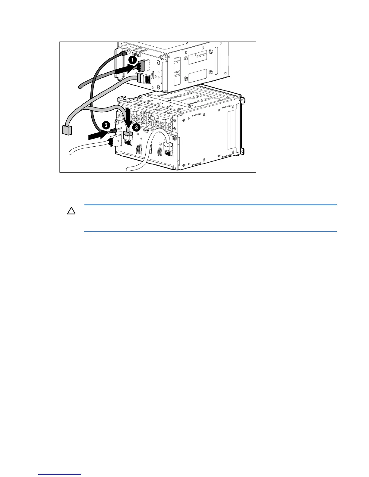
o The "6LFF" labeled connector to the primary hard drive cage
10. Connect the remaining connector to SAS connector B on the system board ("System board components"
on page 11).
11. Slide the optional hard drive cage fully into the bay until it clicks, and then install the screws.
CAUTION: Always populate each media bay with either a device or a blank. Proper airflow can
only be maintained when the bays are populated. Unpopulated drive bays can lead to improper
cooling and thermal damage.
12. Install any hard drives or blanks ("SAS or SATA hard drive option" on page 52).
13. Install the access panel (on page 27).
14. Do one of the following:
o Close or install the tower bezel, as needed.
o Slide the server back into the rack.
15. Power up the server (on page 24).
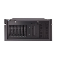
Removable media device options
Identifying guide screws
When installing drives in the removable media bay, guide screws must be installed to make sure the drives
align correctly in the drive cage. HP has provided extra guide screws, 5.25 M3 metric screws and/or HD
6-32 shipping screws, located behind the media bay blank. The metric screws are black.
Installing a half-height or full-height media device
The server includes five removable media bays. The server ships with an optical drive, and the other four
bays have blanks. You can install two full-height devices or up to four additional half-height media devices in
the removable media cage.

 Loading...