System board
The system board is secured with a a total of ten Torx screws. Two of the screws also secure the removable
side bracket, and two other screws secure the I/O bracket.
To remove the system board:
1. Prepare the computer for disassembly (see Preparing to disassemble the computer on page 19).
2. Remove the rear port cover (see Rear port cover on page 23).
3. Remove the stand (see Attaching and removing a stand on page 20).
4. Remove the access panel (see Access panel on page 24).
5. Remove the system board shield (see System board (EMI) shield on page 32).
6. Remove the memory modules (see Memory on page 33).
7. Remove the WLAN module (see WLAN module on page 36).
8. Remove the heat sink (see Heat sink on page 37).
9. Remove the processor (see Processor on page 38).
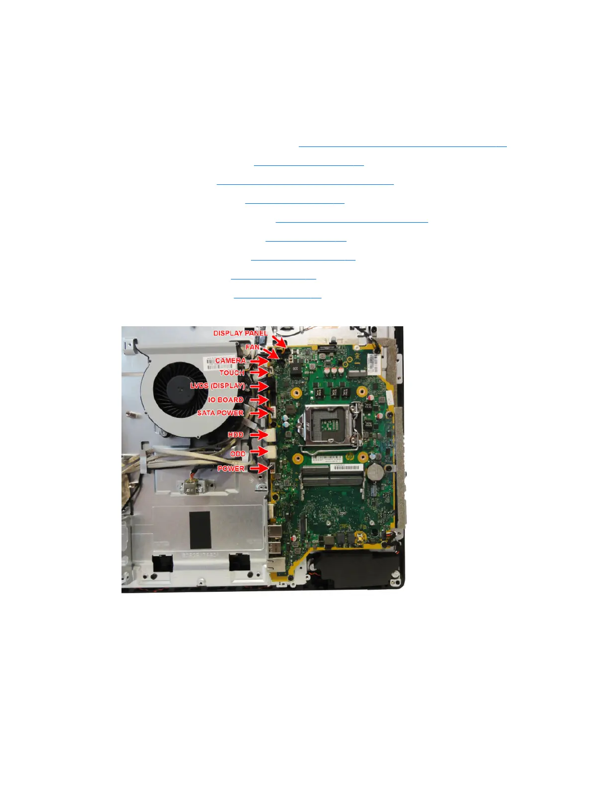
10. Disconnect all cables from the system board, noting their location for reinstallation.
11. Remove the eight Torx screws (1) that secure the system board to the computer.
System board 41