Chapter 3 Installation Guidelines
15
250 N
or
56.25 lbs
@ max
height = 2 m
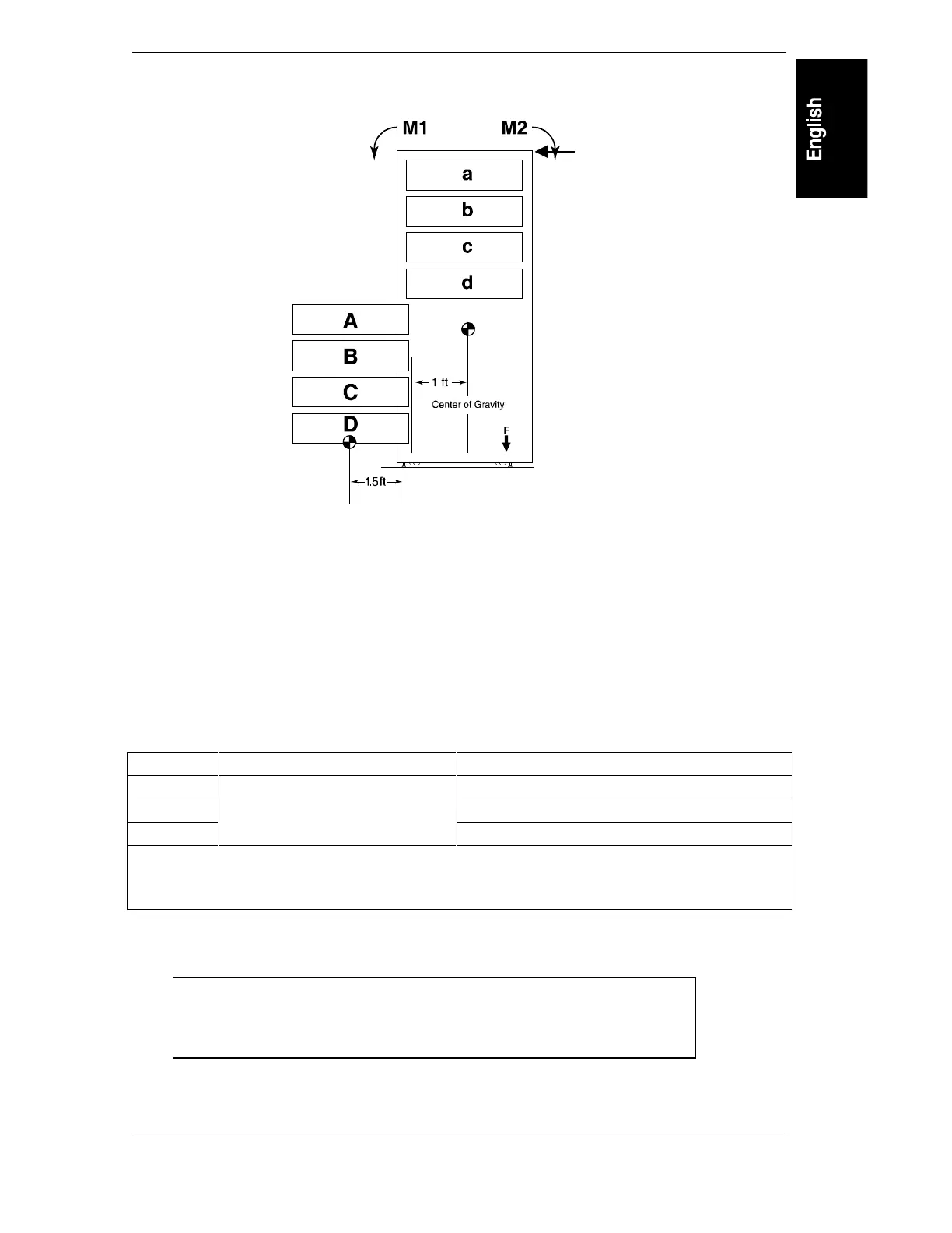
Figure 3-5. Moment Illustration for Slide Mounted Products
Weight and Balance Worksheet:
1. Total the weight of operator serviceable slide-mounted products:
A=________lbs; B=________lbs; C=_________lbs; D=_________ lbs; . . .
2. Total the weight of all fixed and trained service personnel serviceable products:
a=________lbs; b=_________lbs; c=__________lbs; d=_________ lbs; . . .
3. Calculate the moment for both the operator serviceable slide-mounted products (M1) and the
fixed and trained service personnel serviceable products (M2) totals from above:
Model M1 M2
1.25 m -10.46 ft-lbs + (a + b + c + d + ....) * 1.00 ft
1.6 m -49.5.4 ft-lbs + (a + b + c + d + ....) * 1.00 ft
1.96 m
(A + B + C + D ...) * 1.25 ft
-97.2 ft-lbs + (a + b + c + d + ....) * 1.00 ft
M1 = Moment on rack with all operator serviceable slide mounted products extended.
M2 = Moment of all fixed and trained personnel serviceable slide mounted products and rack.
M2 moment calculations assume a 1.00 ft center of gravity for installed products.
If M1 is less than or equal to M2, no additional counter weight is needed.
If M1 is greater than M2, use the formulas below to determine the required counter weight.
Each ballast kit (C2790A) weighs 30 lbs.
Force (in lbs) = M1 - M2 ft-lbs / 2.46 = amount of force required @ 2.46 ft
X = Force lbs / 30 lbs = number of C2790A 30 lbs ballast kits to install, where
“X” is rounded up to the next highest integer, e.g., 1.2 = 2 ballast kits.