4. Remove the battery (see Battery on page 38).
5. Remove the following components:
a. Hard drive (see
Hard drive on page 40)
b. Memory module compartment cover (see
Memory module on page 44)
c. Optical drive (see
Optical drive on page 43)
d. Keyboard (see
Keyboard on page 49)
e. Switch cover (see
Switch cover on page 51)
f. Display assembly (see
Display assembly on page 53)
g. Top cover (see
Top cover on page 56)
h. Power switch assembly (see
Power switch assembly on page 58)
i. System board (see
System board on page 61)
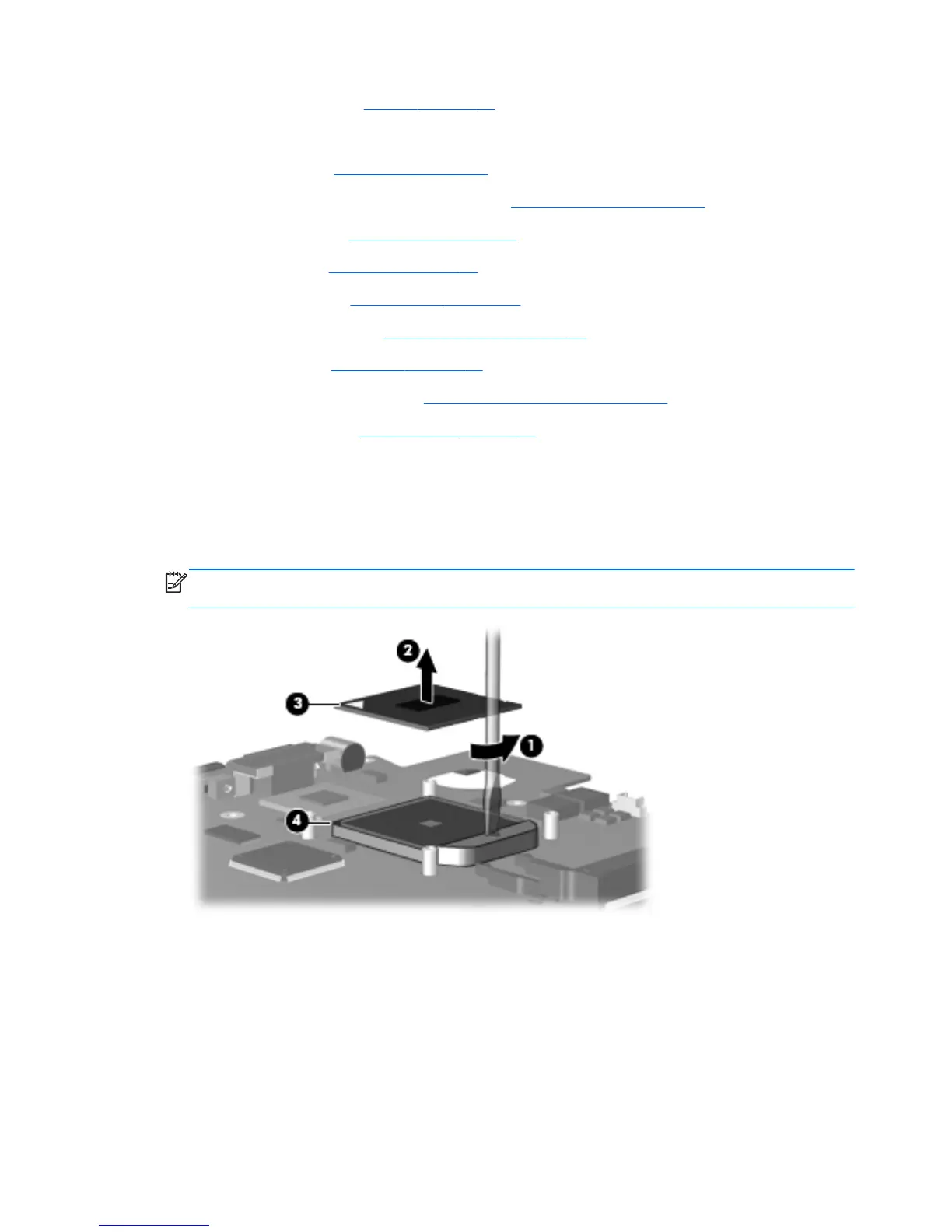
Remove the processor:
1. Use a flat-bladed screwdriver to turn the processor locking screw (1) one-half turn
counterclockwise until you hear a click.
2. Lift the processor (2) straight up and remove it.
NOTE: The gold triangle (3) on the processor should be aligned with the triangle (4) embossed
on the processor socket when you install the processor.
Reverse this procedure to install the processor.
70 Chapter 4 Removal and replacement procedures