System board architecture
This section describes the workstation system architecture.
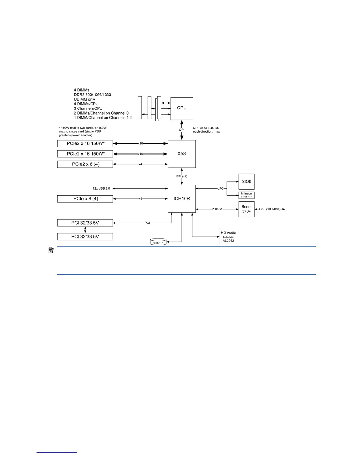
The following figures show the typical system board block diagram for 4–DIMM and 6–DIMM Z400
workstations.
Figure 1-1 4–DIMM system board block diagram
NOTE: The x1, x4, x8, and x16 designators describe the mechanical length of the slot. The number
in parentheses lists the number of electrical PCIe lanes routed to the expansion slot. For example, x16
(8) means that the expansion slot is mechanically a x16 length connector, with eight PCIe lanes
connected.
2 Chapter 1 Product overview ENWW

 Loading...