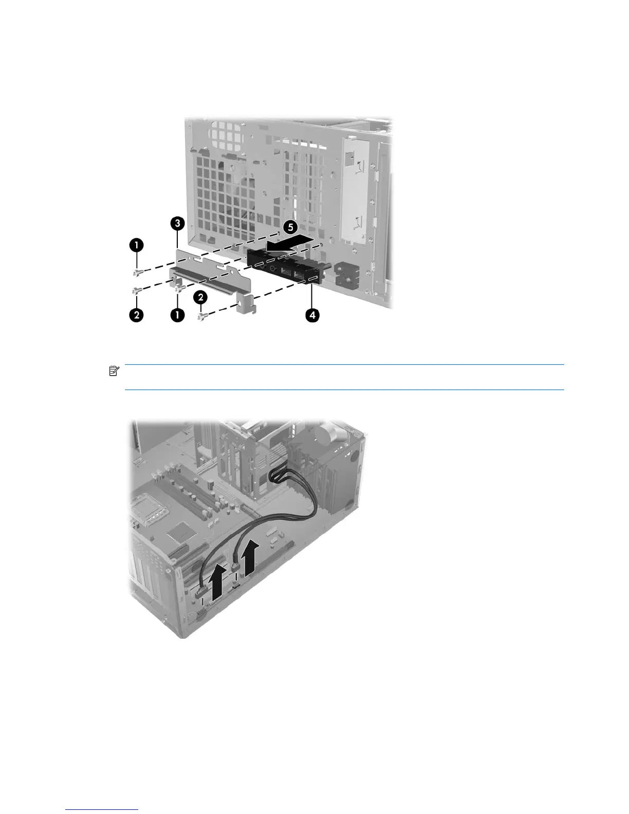
5. Remove the fastening screws from the I/O device assembly and remove it from the chassis as
shown in the following figure.
Figure 5-8 Removing the front panel I/O device assembly
6. Disconnect the front panel I/O device assembly cables from the system board as shown below.
NOTE: Z400s with 6 DIMM slots have an additional cable from the front panel to the 1394a card
that you must also disconnect.
Figure 5-9 Disconnecting the front panel I/O cables
7. Carefully guide the front panel I/O device assembly from the chassis.
76 Chapter 5 Replacing components ENWW
 Loading...