Chapter 4 Electrical Installation Shenzhen Hpmont Technology Co., Ltd.
―20― HD3L Series Controller User Manual
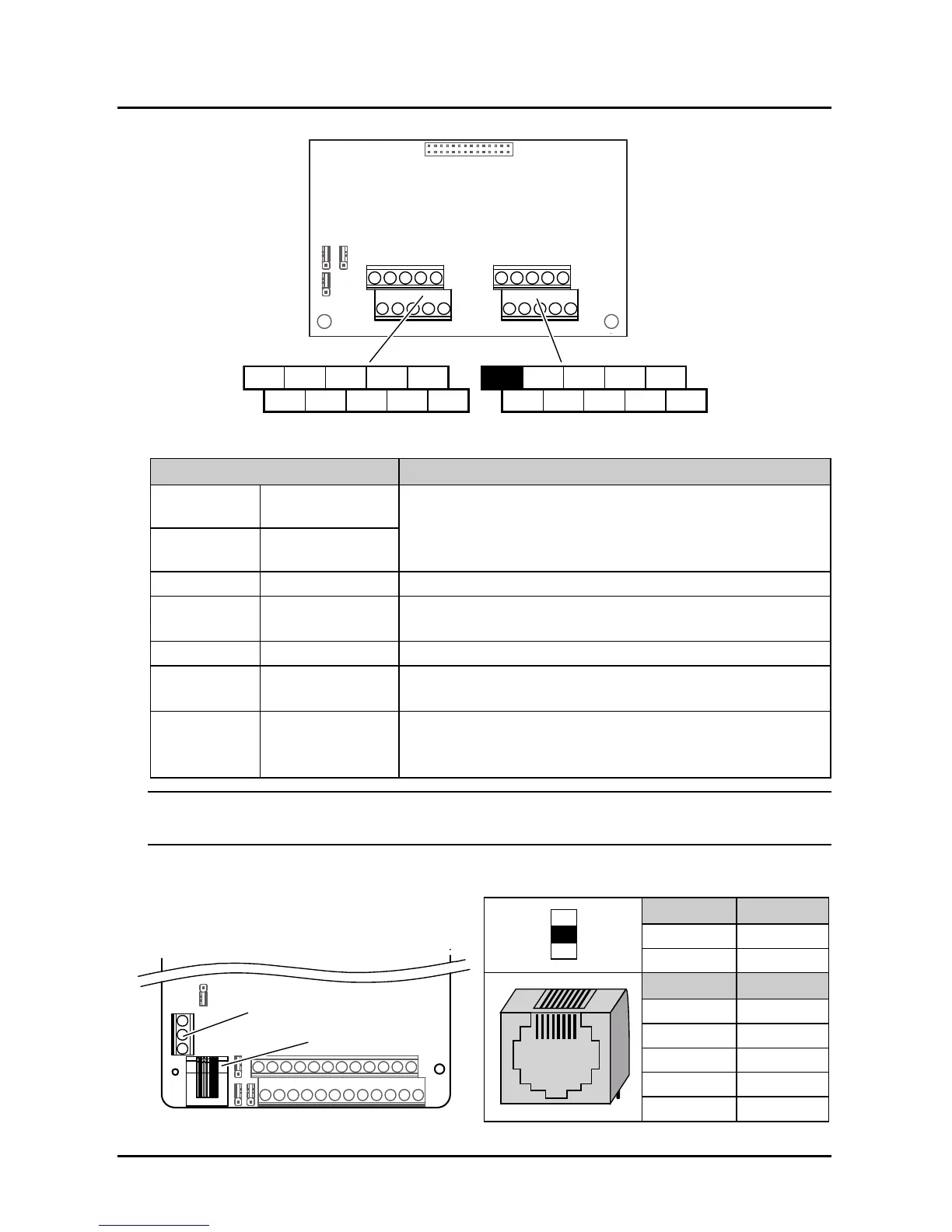
4.4.2 I/O Board Terminal
Figure 4–5 I/O board terminals
Table 4-6 I/O board terminal description
Terminal Description
AI3 Analogue input
Input voltage / current selectable
Input voltage: -10 - +10V (AI3 input impedance 32kΩ; AI4 input
impedance 34kΩ)
Input current: 0 - 20mA (input impedance: 500Ω)
AI4+/AI4-
Analogue difference
input
GND Analogue GND GND isolated with COM
DI7 - DI9 Digital input
Programmable bipolar optional input signal
Input voltage: 0 - 30VDC (input impedance: 4.7kΩ)
P24, COM Digital power supply Digital input use +24V as supply, max. output current is 200mA
SEL
Digital input
common terminal
SEL and P24 are connected by default
• Disconnected SEL and P24 when use external power to drive DI7 - DI9
R2A/R2B/R2C
R3A/R3B/R3C
R4A/R4B/R4C
Relay output
Programmable output, contact rating: 250VAC/3A or 30VDC/1A
• RB, RC: normally closed; RA, RC: normally open
Note:
Limit the current within 3A if the relay terminal is to connect to AC 220V voltage signal.
4.4.3 Modbus Communication Terminal
Do not use communication terminal and RJ45
simultaneously.
Terminal Description
A 485+
B 485-
Pin Difinition
1,3 +5V
2 485+
4,5,6 GND
7 485-
8 Unused
I/O Board
AI3 AI4+ DI7 DI8 DI9 R2A R3A R4AR3B
GND
P24 SEL
COM R2C R4CAI4- R2B R3C R4B
Terminal Terminal
RJ45
Control Board
Terminal
 Loading...
