LP-605 Rev. 000 Rel. 009 Date 8.16.18
30
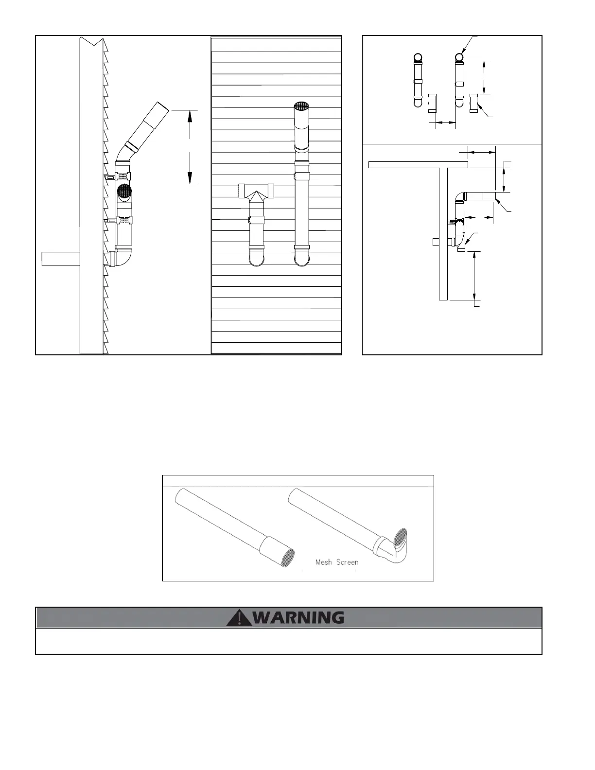
Screen Installation
After connecting the intake air and exhaust vent pipes, it is required to install the included screens into the exhaust vent and intake pipe
terminations to prevent damages to the unit due to blockages. See Figure 24 for installation detail.
Figure 23 - Screen Installation - NOTE: Vent termination elbow is meant to be installed open end facing the ground. Orientation in Figure 24 is meant
to demonstrate proper Vent Screen installation ONLY.
NOTES:
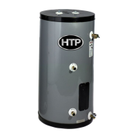
A. For every 1” of overhang, the exhaust vent must be located 1” vertical below overhang (overhang means top of building structure and not
two adjacent walls [corner of building]).
B. Typical installations require 12” minimum separation between bottom of exhaust outlet and top of air intake.
C. Maintain 12” minimum clearance above highest anticipated snow level or grade (whichever is greater).
D. Minimum 12” between vents when installing multiple vents.
E. 12” minimum beyond air intake.
24.00
LP-325-OO
02/04/15
Intake
Exhaust
A
1
FRONT VIEW
SIDE VIEW
LP-325-PP
EXHAUST
AIR INTAKE
F
E
D
C
AIR INTAKE
B
Figure 22 - Horizontal (Snorkel) Venting
Do not connect any other appliance vents to the water heater exhaust vent or intake pipes. Failure to do so could result in property damage,
severe personal injury, or death.
 Loading...