LP-605 Rev. 000 Rel. 009 Date 8.16.18
41
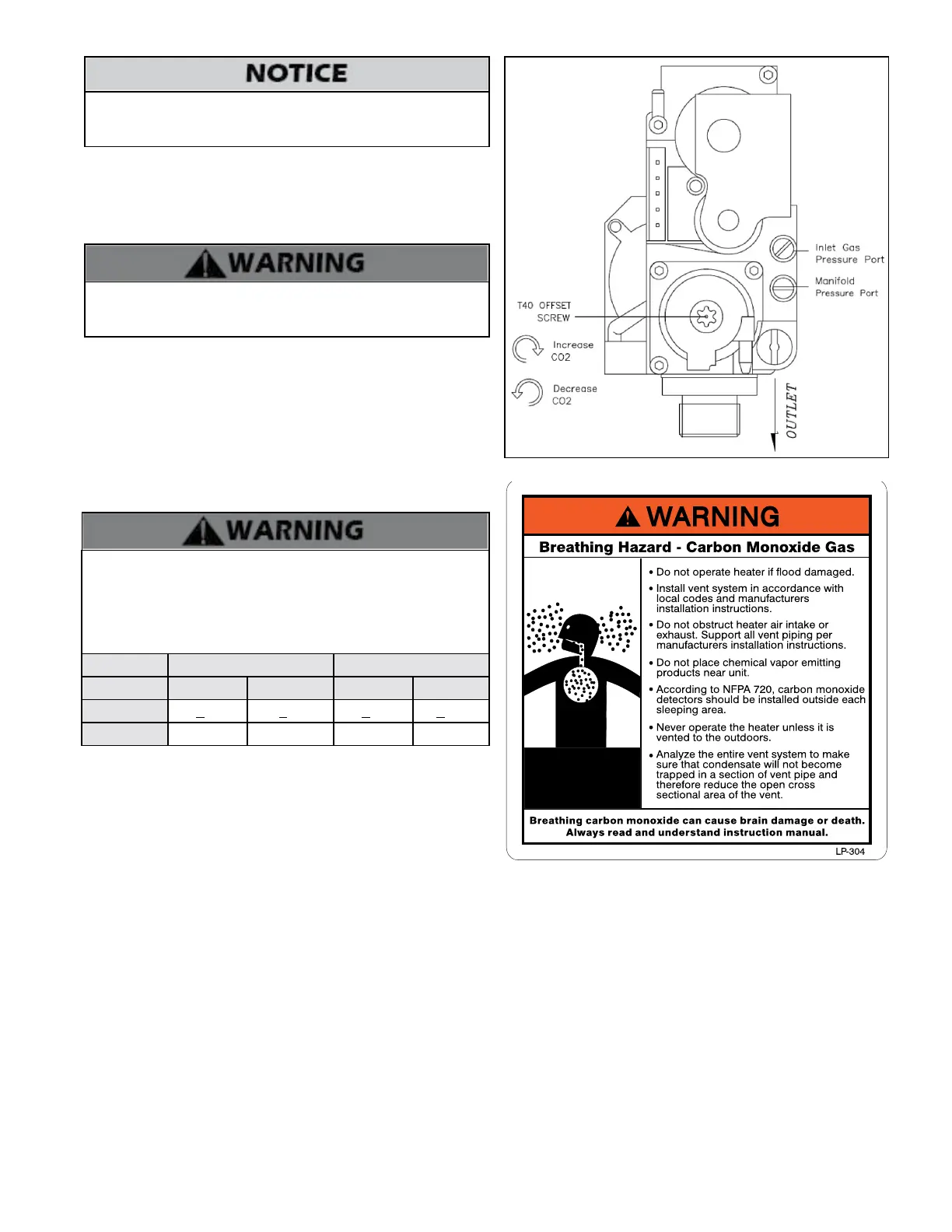
Figure 43 - Gas Valve Detail
Do not re (operate) the water heater until all connections have
been completed and the heat exchanger is lled with water. Doing
so will damage the water heater and void the warranty.
F. Setting and Verifying the Combustion Setting
1. After the water heater has red, ip DIP switch three (3) in Group 1 to
the ON position (low re). Proceed to check heater combustion values.
NOTE: Use a calibrated combustion analyzer to ensure CO and CO2
values are within the range shown in Table 24.
It is required to use a calibrated combustion analyzer to verify nal
adjustment according to the combustion chart (Table 24). Failure to
do so could result in serious personal injury or death.
If the readings obtained are lower or higher than the combustion
readings in Table 24, use a T40 Torx screwdriver to adjust the oset
screw in a clockwise (positive) or counterclockwise (negative) direction
(approximately 1/4 turn). See Figure 44. Check your combustion values.
Repeat this procedure until the values obtained on the calibrated
combustion analyzer agree with those stated in Table 24.
NOTE: If the heater makes a whistling sound (harmonics) at low re,
adjust the oset screw in a clockwise (positive) direction (approximately
1/8 turn). Check your combustion values and ensure they agree with
those stated in Table 24 before proceeding.
It is very important that the combustion system be set within the
recommended CO measurements listed in Table 24. Visually looking
at the burner does not determine combustion quality. Failure to
measure combustion with a calibrated combustion analyzer and set
the throttle within the recommended CO measurements could result
in property damage, severe personal injury, or death.
Natural Gas LP Gas
Fan Speed Low High Low High
CO PPM <30 <50 <50 <100
CO2 (%) 8 - 9 1/2 8 1/2 - 10 9 - 10 1/2 9 1/2 - 11
Table 24 - Combustion Settings
2. When low re settings have been obtained, ip DIP switch three (3)
in Group 1 to its original (OFF) position. This will return the heater to
normal operation.
3. Open a hot water faucet or faucets and run hot water at more than
2 gpm to put the water heater into high re. Again check combustion
readings with a calibrated combustion analyzer.
NOTE: DO NOT adjust the gas valve oset screw at high re. The oset
screw is only used to adjust combustion values at low re.
4. When complete, turn o the hot water faucet(s). Allow water heater
to operate normall. Ensure it is operating properly.
5. Use a Phillips Head screwdriver to reinstall the heater top cover.
 Loading...