10
KNOW YOUR WELDER
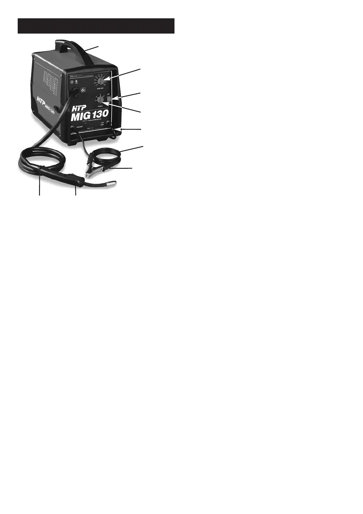
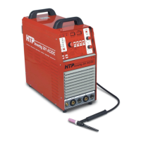
Handle – Rugged, top mounted handle
allows for easy transport of your welder.
Wire Speed Control – Use this dial to adjust
the speed at which the welder feeds wire to
the gun. 1 is the slowest wire feed speed, 10 is
the highest. You will need to adjust or “tune-
in” your wire speed for different welding con-
ditions (thickness of metals, gas -vs- gasless
welding, metal type, wire size, etc.). When the
wire speed is properly “tuned-in” the welding
wire will melt into the material you are weld-
ing as quickly as it is fed through the welding
gun.
Voltage Selector – This four position dial
adjusts the voltage or “heat” of your welder. 1
is the lowest and 4 is the highest. Different
materials and material thickness will require
different voltage settings. You will need to
adjust your voltage accordingly for different
welding conditions. By properly adjusting
your voltage settings and wire feed speed,
you will enable clean, precision welds. (Refer
to the Suggested Settings Chart on p.33 of
this manual OR on the inside of the door of
the welder.)
Power Switch – This switch turns the welder
ON and OFF. (Make sure the power switch is
in the OFF position before performing any
maintenance on the welder.)
Power Cord – This is a standard, grounded
120 volt power cord. (Make sure you are
using a properly grounded 120 VAC, 60Hz,
single phase, 20 amp power source.)
Ground Clamp – Attaching the ground
clamp to your work piece “completes” the
welding current circuit. You must attach the
ground clamp to the metal you are welding.
If the ground clamp is not connected to the
metal work piece you intend to weld, the
welder will not have a completed circuit and
you will be unable to weld. A poor connec-
tion at the ground clamp will waste power
and heat. Scrape away dirt, rust, scale, oil or
paint before attaching the ground clamp.
Ground Cable – The ground cable connects
the ground clamp to the internal workings of
the welder.
Welding Gun and Cable – The welding gun
controls the delivery of the welding wire to
the material to be welded. The welding wire
is fed through the welding cable and welding
gun when the welding gun trigger is pulled.
You will need to install a contact tip and
welding nozzle to the end of the welding
gun, as described later in this manual, prior to
welding.
Welding Terms
Now that you are familiar with the main parts
of the welder, make note of the following
terms. You will see them used throughout
this manual.
weld puddle: The localized volume
of molten metal in a weld prior to its
solidification.
weld angle: The angle of the welding wire, as
it extends from the welding gun, in relation
to the item being welded.
slag: The protective coating that forms on
the surface of molten metal.
arc: A sustained luminous discharge of elec-
tricity across a gap in a circuit.
welding bead: The extended build up of a
weld, made by pushing or pulling the weld
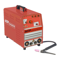
Figure 1. Model HTP MIG 130
Welding
Gun
Ground
Clamp
Power
Cable
Ground
Cable
Voltage
Selector
Power
Switch
Wire
Speed
Gun Cable
Handle