14
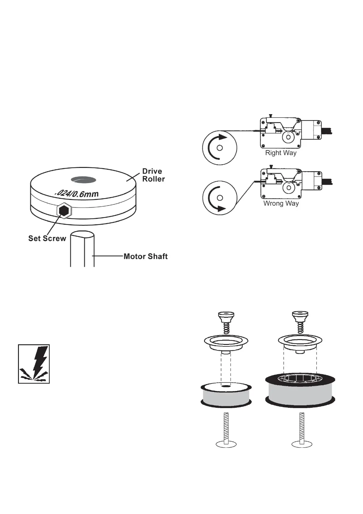
Note: The drive roller has two wire size grooves
built into it. When installing the drive roller the
number stamped on the drive roller for the
wire size you are using should be facing away
from you. If you can read the wire size you are
using on the drive roller, it is installed back-
wards. Use only the proper size drive roller
when using your welder.
4. Find the side of the drive roller that is
stamped with the same wire diameter as
that of the wire being installed (see Figure
4, and if in metric, see DESCRIPTION). Push
the drive roller onto the motor shaft, align-
ing the set screw with the flat side of the
drive shaft. Make sure the side stamped
with the desired wire diameter is away
from you.
5. Slide the roller onto the shaft so that the
groove in the roller lines up with the inlet
tube and the welding gun liner.
6. Tighten the set screw, while holding the
drive roller in place.
INSTALL THE WELDING WIRE
WARNING
Electric shock can kill! Always turn the POWER
switch OFF and unplug the power cord from
the ac power source before installing wire.
1. Remove the nozzle and contact tip from
the end of the gun assembly.
2. Make sure the proper groove on the drive
roller is in place for the wire being installed.
If the proper groove is not in place, change
the drive roller as described above.
3. Unwrap the spool of wire and then find the
leading end of the wire (it goes through a
hole in the outer edge of the spool and is
bent over the spool edge to prevent the
wire from unspooling), BUT DO NOT
UNHOOK IT YET.
4. Place the spool on the spindle in such a
manner that when the wire comes off the
spool, it will look like the top illustration in
Figure 5. The welding wire should always
come off the top of the spool into the drive
mechanism.
5. If you are installing a four-inch spool of
wire, install the drive brake hardware on
the top of the spool of wire according to
figure 6A. If you are installing an eight-inch
spool, install the spindle adapter and drive
brake hardware as shown in Figure 6B. The
purpose of the drive brake is to cause the
spool of wire to stop turning at nearly the
same moment that wire feeding stops.
Figure 4. Drive Roller
Figure 5. Wire Installation
Figure 7A. Drive
Brake Hardware
Installation
Figure 7B. Spindle
Adapter and Drive
Brake Installation