16
SET THE WIRE DRIVE TENSION
WARNING
To reduce the risk of arc flash, make certain
that the wire coming out of the end of the
gun does not come in contact with work
piece, ground clamp or any grounded materi-
al during the drive tension setting process or
arcing will occur.
1. Pull the trigger on the gun.
2. Turn the drive tension adjustment knob
clockwise, increasing the drive tension
until the wire seems to feed smoothly
without slipping.
When set correctly, there should be no slip-
page between the wire and the drive roller
under normal conditions. If an obstruction
occurs along the wire feed path, the wire
should then slip on the drive roller.
After the tension is properly adjusted, the
quick release drive tensioner may unlocked
and relocked and no radjustment of the drive
tension adjustment knob will be necessary
(unless the diameter or type of wire is
changed).
INSTALLING ALUMINIUM WIRE
Install aluminium wire the same as steel wire,
but with the following exceptions:
1. Install a plastic liner (PN15044) in the
welding gun.
2. Adjust the drive tension VERY carefully.
Aluminium wire is very sensitive to slight
changes in drive tension.
Note: For welding aluminium with this unit,
5356 alloy wire is recommended because of
its superior feedability. A plastic liner is need-
ed. When welding with softer aluminium
alloys, you may experience feed problems.
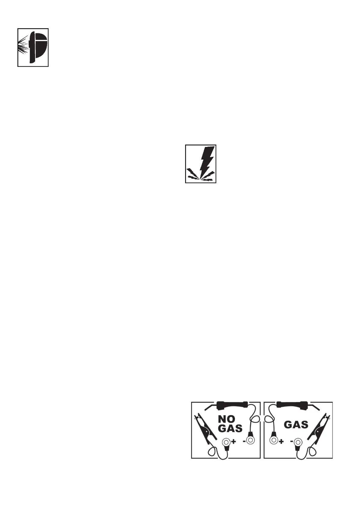
CHANGE POLARITY
This welder allows you to change the welding
current polarity. Select Straight Polarity for
welding with Flux Core Wire (FCAW). Select
Reverse Polarity for MIG welding (GMAW)
when using mild steel, stainless steel or sili-
con bronze wire. Reverse polarity is also sug-
gested with some flux core wire used in hard
facing.
Change the polarity of your welder according
to the following procedure steps. Figure 8
shows what the polarity block should look
like for each polarity setting.
WARNING
Electric shock can kill! Always turn the power
OFF and unplug the power cord from the ac
power source before changing polarity.
CAUTION
Do not use a ratchet, crescent or other lever
type wrench to tighten knobs on the polarity
block. The nuts must be hand tightened only.
Too much torque applied to one of the knobs
could cause the knob to break off.
1. Remove the retaining knobs from the +
and - mounting posts on the Gas/No Gas
Board, located just below the drive motor
on the inside of your welder.
A. For Gasless (FCAW) welding, mount the
Ground Clamp ring terminal to the “+”
mounting post and the Torch ring ter-
minal to the “-”mounting post.
B. For MIG (GMAW) welding, mount the
Ground Clamp ring terminal to the “-”
mounting post and the Torch ring ter-
minal to the “+” mounting post.
See configuration shown in Figure 7.
Figure 7. Changing Polarity
 Loading...