10
The installation of all horizontal and vertical piping may not reduce the performance or rating of any
structural member or fire rated assembly. Adhere to all applicable local codes and ordinances.
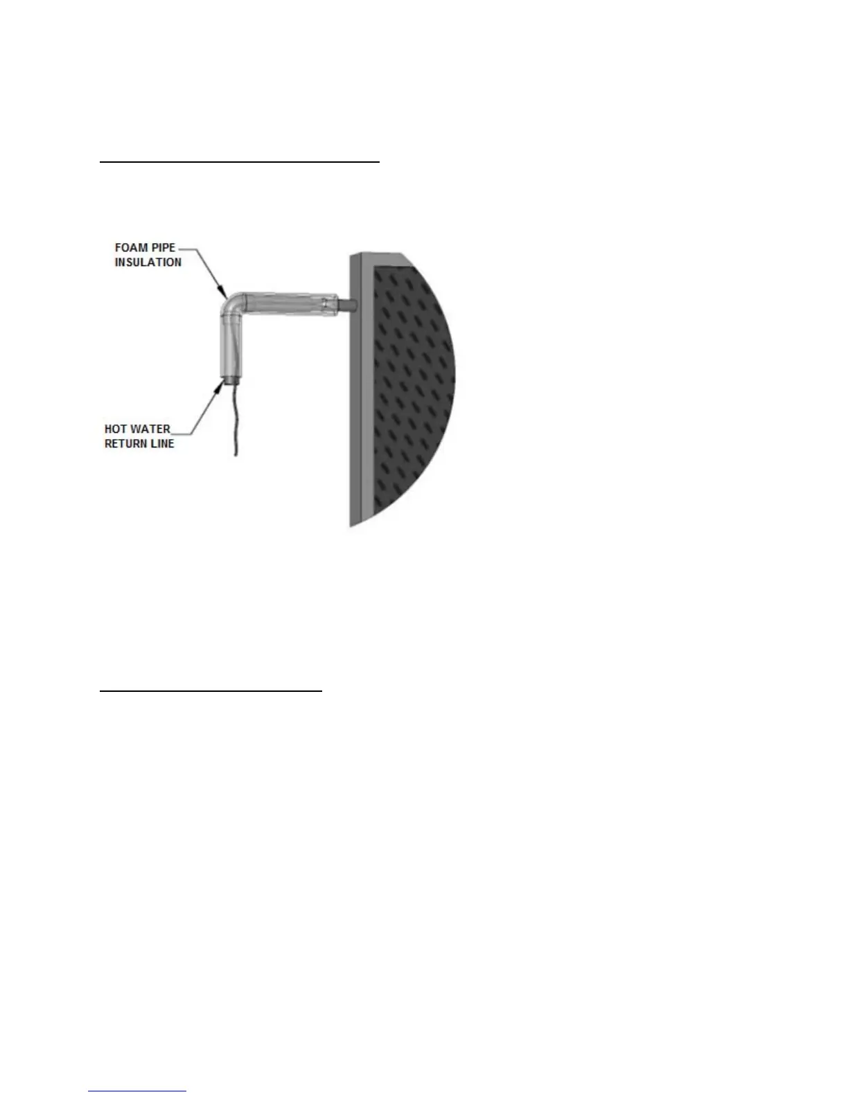
L. COLLECTOR SENSOR PLACEMENT
The collector sensor must be located on the hot water return line as close to the collector as possible.
Some collectors have insertion areas to measure temperatures more accurately at the collector manifold.
Sensors are typically accurate to +/- 1/2
o
F if
properly installed and weatherized. To
maximize sensor accuracy, attach the
flanged portion of the sensor to the collector
header pipe with a stainless steel hose
clamp. Wire nuts used to connect the
sensor and low voltage wiring shall be all
plastic, sealed with silicone, and thoroughly
wrapped in electrician’s tape.
The low voltage wiring used to connect the
sensors to the controller should be a
minimum 18 AWG. The wiring should be
bare or tinned copper, two conductor, PVC
insulated, with a PVC UV rated gray jacket
suitable for exterior use. Use Eastman Wire
& Cable no. 5704, Beldon Wire and Cable
no. 8461 or equal.
The sensor “bundle” must be placed under
the rubber pipe insulation covering the
collector header. Thoroughly wrap and weatherize the insulation with electrician’s tape or insulation tape
as provided by the manufacturer (Rubatex Insul-Tape or equal).
PART 3: WATER HEATER INSTALLATION
A. INSTALLATION CHECKLIST
Location
• Sufficient room to service water heater
• Provisions made to protect area from water damage
• Centrally located to fixtures
• Protected from freezing temperatures
• Area free of flammable vapors
Potable Water Supply
• All related piping free from leaks
• Thermal expansion tank installed
• Water heater and fixtures have been properly purged of air
• ASSE 1017 rated thermostatic mixing valve (if water temperature is set above 120
o
F)
Relief Valve
• Temperature and Pressure relief valve properly installed and discharge line runs to open drain
• Discharge line not exposed to freezing temperatures
• Discharge line constructed of copper
Figure 4 – Sensor Placement – LP-199-O