19
LP-454 REV. 1.6.15
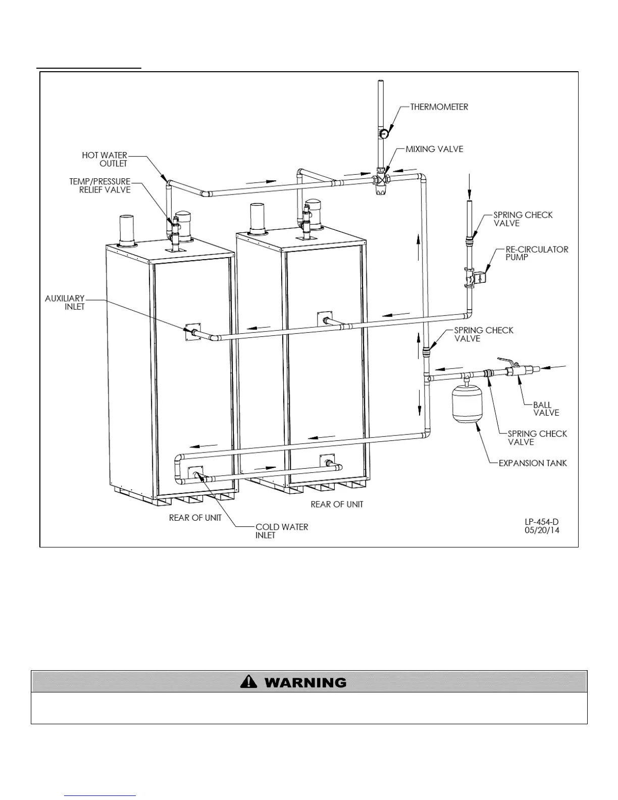
H. PIPING DIAGRAMS
Figure 5 – Reverse Manifold and Piping Diagram
NOTES:
1. Minimum pipe size should match unit connection size. Upsize pipe accordingly if greater flow is required.
2. A thermal expansion tank suitable for potable water must be sized and installed within this piping system between the backflow preventer and the cold
water inlet.
3. Gas line must be rated to the unit maximum input capacity. Unit must have 10 feet of pipe after gas regulator.
4. All circulators should have an integral flow check.
5. Check with air handler manufacturer for proper sizing.
6. This drawing is meant to demonstrate system piping only. The installer is responsible for all equipment and detailing required by local codes. In
Massachusetts, you must install a vacuum relief valve per 248 CMR. With air handlers, outdoor reset is available with an outdoor sensor. See Part 8,
Section D.
The piping will not support the weight of the water heater circulator pump. Refer to the pump manufacturer’s installation instructions to
properly support the circulator pump. Failure to comply with these instructions could result in substantial property damage, severe
personal injury, or death.